What Ultrasonic Thickness Testing Measures
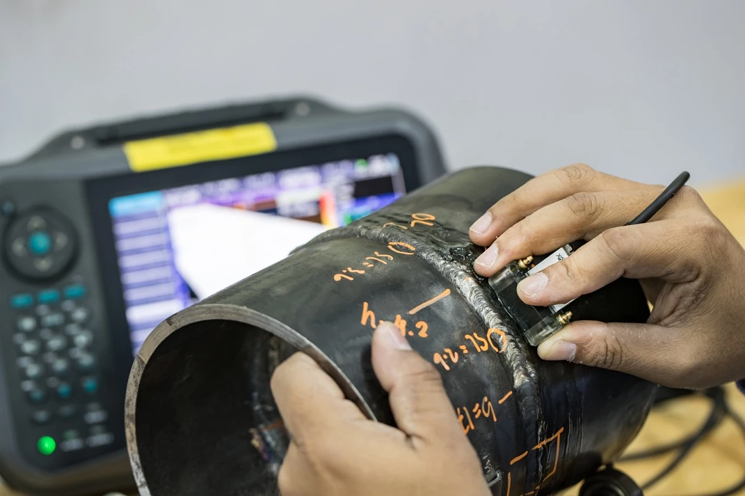
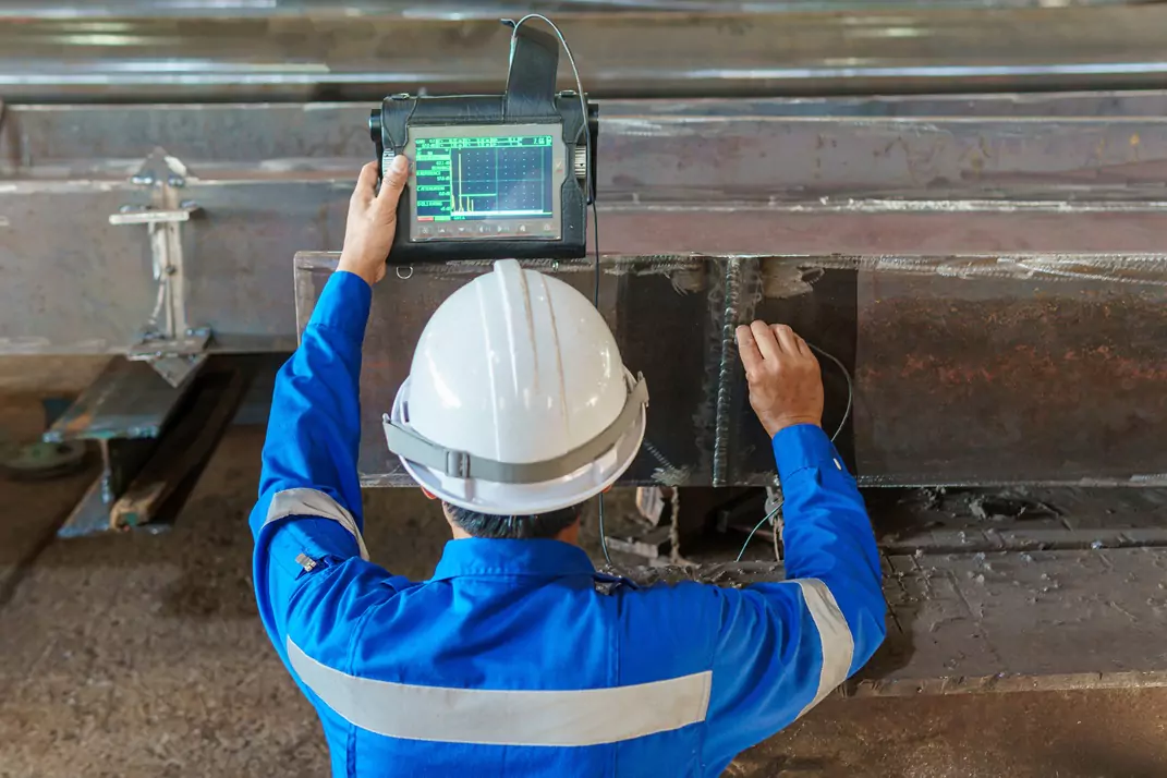
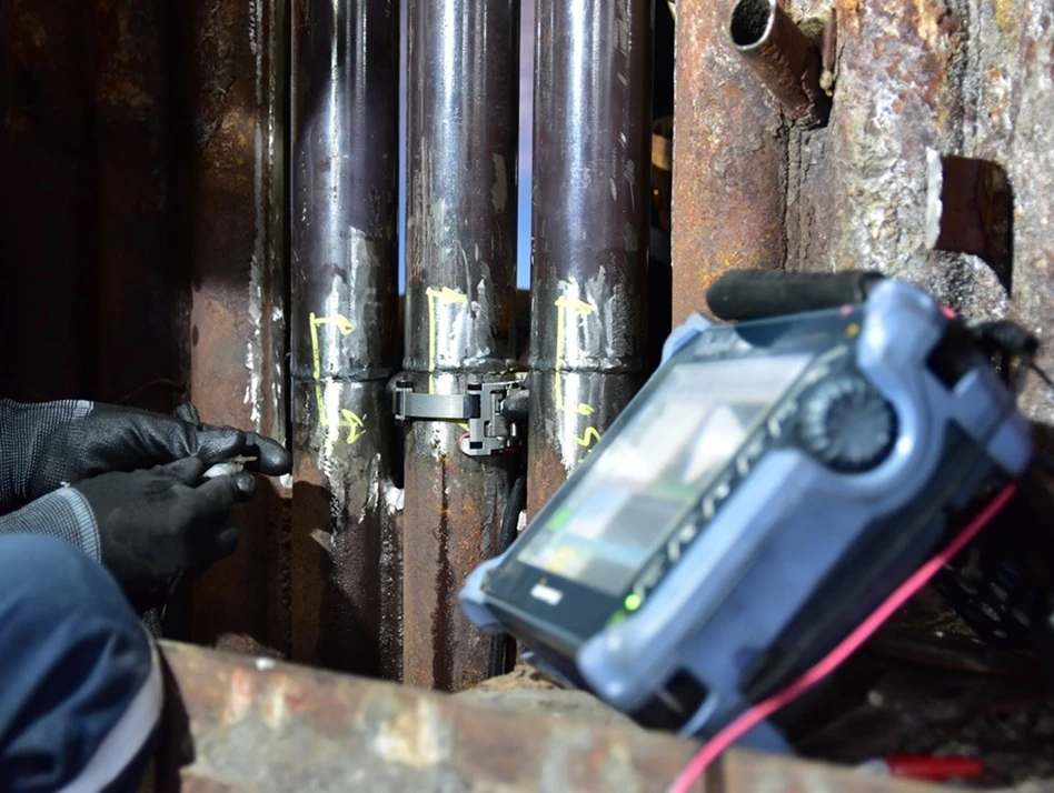
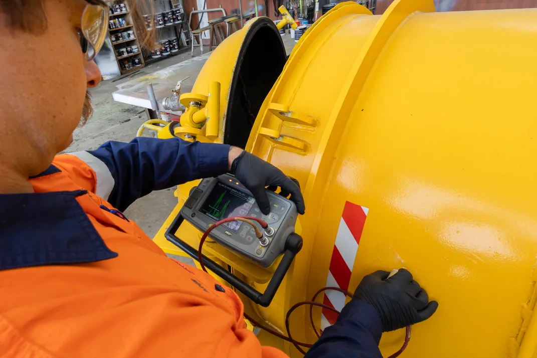
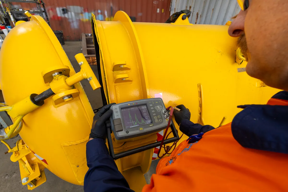
Ultrasonic thickness testing measures how much metal is left in a wall, from one side, without cutting, drilling or shutting the equipment down. It is one of the most common methods for tracking corrosion and erosion on pressure vessels, piping, tanks and structures. Where corrosion is localised, corrosion mapping scans a whole area instead of single points. Both are explained below.
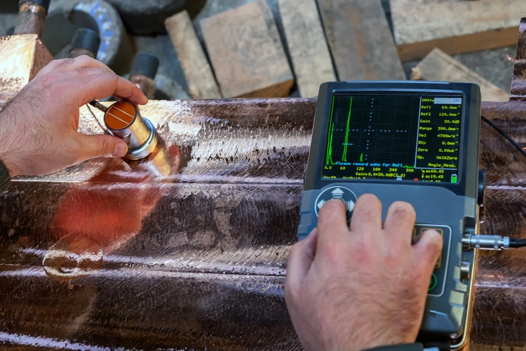
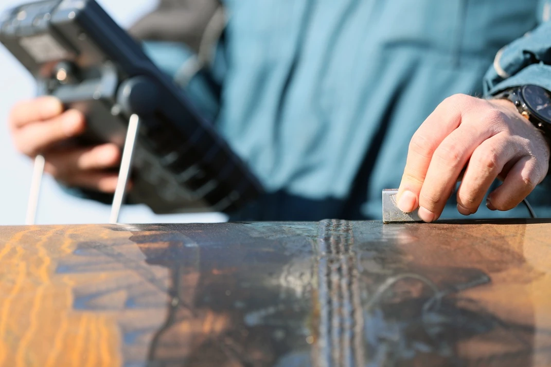
The principle is simple. A probe sends a pulse of high-frequency sound into the metal. The sound travels to the far wall, reflects and returns. The instrument times the round trip, and because sound moves through a given material at a known speed, the time gives the thickness. This is called the pulse-echo method.
Because only one side needs to be reached, readings can be taken on equipment that is full, pressurised and running, as long as the surface is accessible and within the probe's temperature limits. Recognised practices for the method include ASTM E797 and ISO 16809. Standards are revised, and requirements change between editions. Always check which edition your contract, drawing or regulator cites before relying on any requirement.
Calibration and Sound Velocity
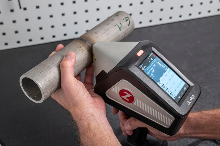
The measurement is only as good as the sound velocity it assumes. Sound travels at different speeds in carbon steel, stainless steel, aluminium and cast iron. If the instrument is set for the wrong material, every reading is wrong by the same proportion, and nothing on the screen warns you.
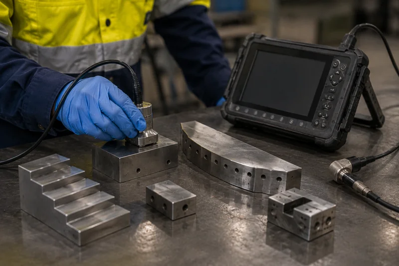
That is why the instrument is calibrated on reference blocks of known thickness, made from the same or an equivalent material, before the survey and checked during and after it. A two-point calibration, on a thin and a thick step, corrects both velocity and the probe's own delay.
Temperature matters too. Sound velocity changes as metal heats up, and standard probes and couplants are not made for hot surfaces. Readings on hot equipment need high-temperature probes and couplant, short contact times, and correction for the temperature. Otherwise readings taken hot are not comparable with readings taken cold at the last shutdown.
Probes, Coatings and the A-Scan
Dual-element probes are the usual choice for corrosion work. One element transmits and the other receives, which gives good performance on rough, pitted back walls and on thin remaining wall, which is where corrosion surveys need it.
Coatings are a common source of error. A basic reading through paint adds the coating to the steel, at the wrong velocity, and overstates the remaining wall. Echo-to-echo techniques measure between successive back-wall echoes within the steel, so the coating drops out of the measurement, and sound, well-bonded paint can usually stay in place.
An A-scan display shows the actual ultrasonic signal, not just a number. That matters because a digital-only reading can't tell a true back-wall echo from a lamination, an inclusion, or a doubled reading on thin material. A lamination halfway through a plate can read as severe wall loss when the plate is actually full thickness. With the waveform on screen, the technician can see which echo is being measured and investigate anything unusual.
For the wider range of ultrasonic techniques, including flaw detection in welds, see our article on contact, immersion and TOFD ultrasonic techniques.
Spot Readings, Grids and Monitoring Locations
Most thickness programmes are built on repeat readings at fixed points, usually called condition monitoring locations (CMLs) or thickness monitoring locations. Each is marked on a drawing, and often on the equipment itself, so the next survey measures exactly the same spot.
Locations are chosen where deterioration is expected: the bottom of horizontal vessels, liquid-vapour interfaces, nozzles, elbows and tees, downstream of control valves and injection points, and areas a previous survey flagged. At each location, a small grid of readings is often taken and the minimum recorded.
The value of the data comes from repeatability. A reading is useful once; the same reading taken the same way at the same place over several surveys shows a trend, and the trend is what supports decisions.
Corrosion Rate and Remaining Life
Two calculations turn thickness readings into decisions.
Corrosion rate is the metal lost between two surveys divided by the time between them. Comparing the latest reading with the original thickness gives a long-term rate. Comparing it with the previous survey gives a short-term rate, which shows whether things have recently sped up.
Remaining life is the metal still available above the minimum required thickness, divided by the corrosion rate. The minimum required thickness comes from the design calculation for the equipment's pressure and temperature, under standards such as AS 1210 for vessels or AS 4041 for piping. It should be set by an engineer, not estimated in the field.
These figures feed directly into in-service inspection decisions under AS/NZS 3788, including whether an inspection interval can be held, extended or must be shortened. Our comparison of API 510 and AS/NZS 3788 covers how the two codes use remaining life differently.
Why Spot Readings Miss Pitting
A thickness probe measures an area roughly the size of a fingertip. A vessel or pipe circuit has square metres of wall. Even a thorough survey of spot readings measures a very small fraction of the surface.
That works when corrosion is general, thinning the wall fairly evenly, because any reading represents its neighbours. It fails when corrosion is localised: isolated pits, grooving along the bottom of a line, erosion downstream of a fitting, or attack under deposits. A deep pit a few centimetres from a monitoring location can go unmeasured survey after survey.
If the damage mechanism is likely to be localised, or spot readings show a large scatter, more coverage is needed.
Corrosion Mapping: Full Coverage of an Area
Corrosion mapping replaces individual points with a continuous scan. The probe, or a phased array probe covering a wider strip, is moved across the surface with a position encoder, and the instrument records a thickness value for every position. The result is a colour-coded C-scan map of the whole area, showing where the wall is thinnest, the shape and extent of the damage, and features such as laminations.
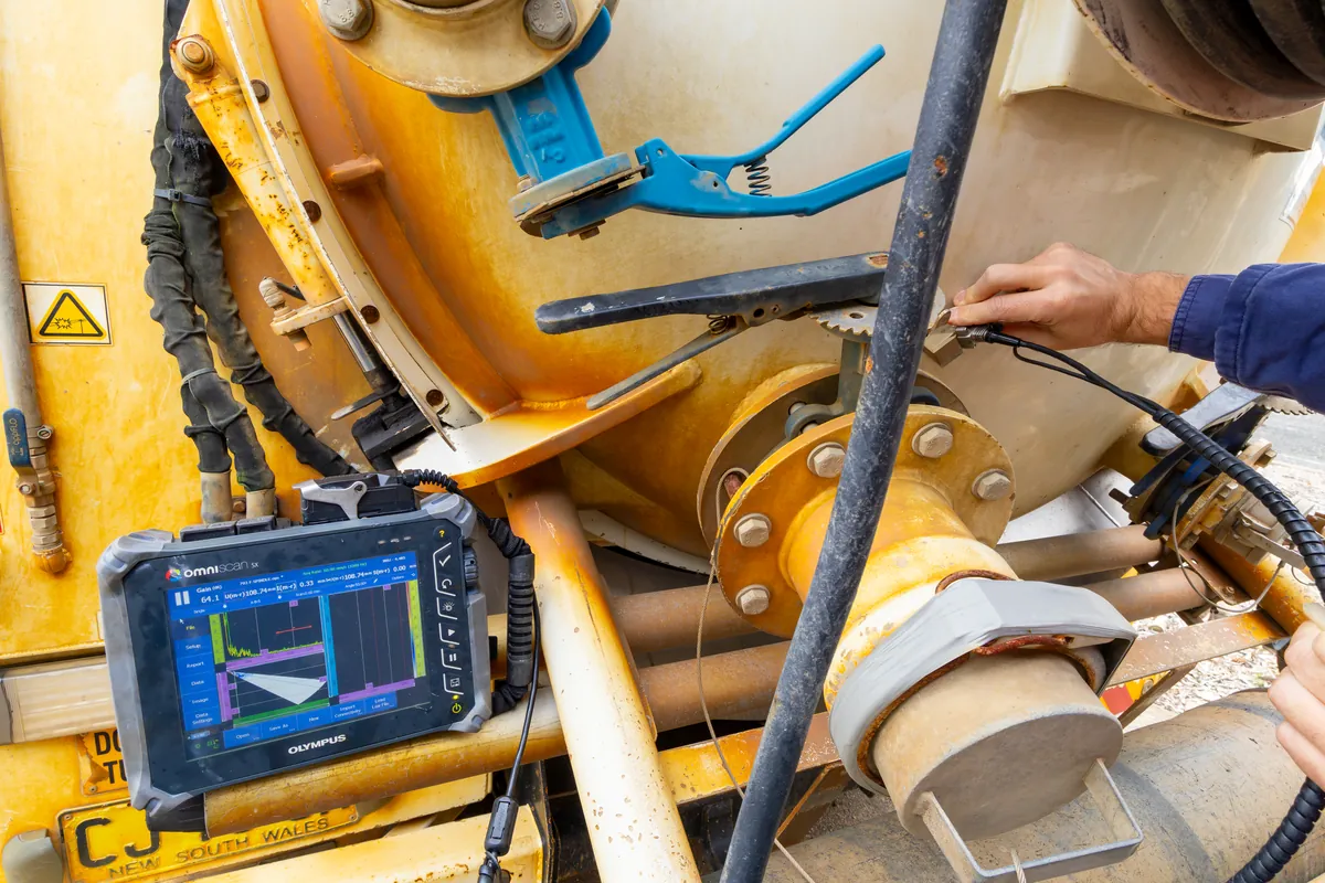
Mapping has three main advantages over spot readings. It finds the true minimum, not the minimum of the points you happened to choose. It shows the pattern, which helps identify the damage mechanism. And because the data is recorded and positioned, the next survey can be compared area for area, not just point for point.
| Spot readings | Corrosion mapping | |
|---|---|---|
| Coverage | Individual points at monitoring locations | Every position across the scanned area |
| Speed | Fast; many locations per shift | Slower per square metre |
| Output | A thickness value per location | A positioned C-scan map plus minimum thickness |
| Finds localised pitting | Only if a point lands on it | Yes, within the scanned area |
| Best use | General corrosion and routine trending | Localised damage, critical areas, baselines |
It takes longer per square metre and needs reasonable surface access, so it is usually aimed at the areas that matter most: known corrosion zones, high-consequence equipment, or areas where spot readings raised questions. For storage tank floors, which have their own screening methods, see tank floor inspection.
Limits of the Method
Ultrasonic thickness testing is reliable when its limits are respected.
- Very thin material can be hard to measure accurately with a standard probe, and readings can double.
- Small-diameter pipe curvature makes probe contact harder; probe choice and technique matter.
- Rough or heavily corroded outer surfaces scatter sound and may need light preparation before readings are reliable.
- Thick, damaged or disbonded coatings can defeat echo-to-echo techniques.
- Gauges versus flaw detectors: a simple digital gauge is quick for routine readings, but an instrument with an A-scan is better where laminations, pitting or unusual signals are likely.
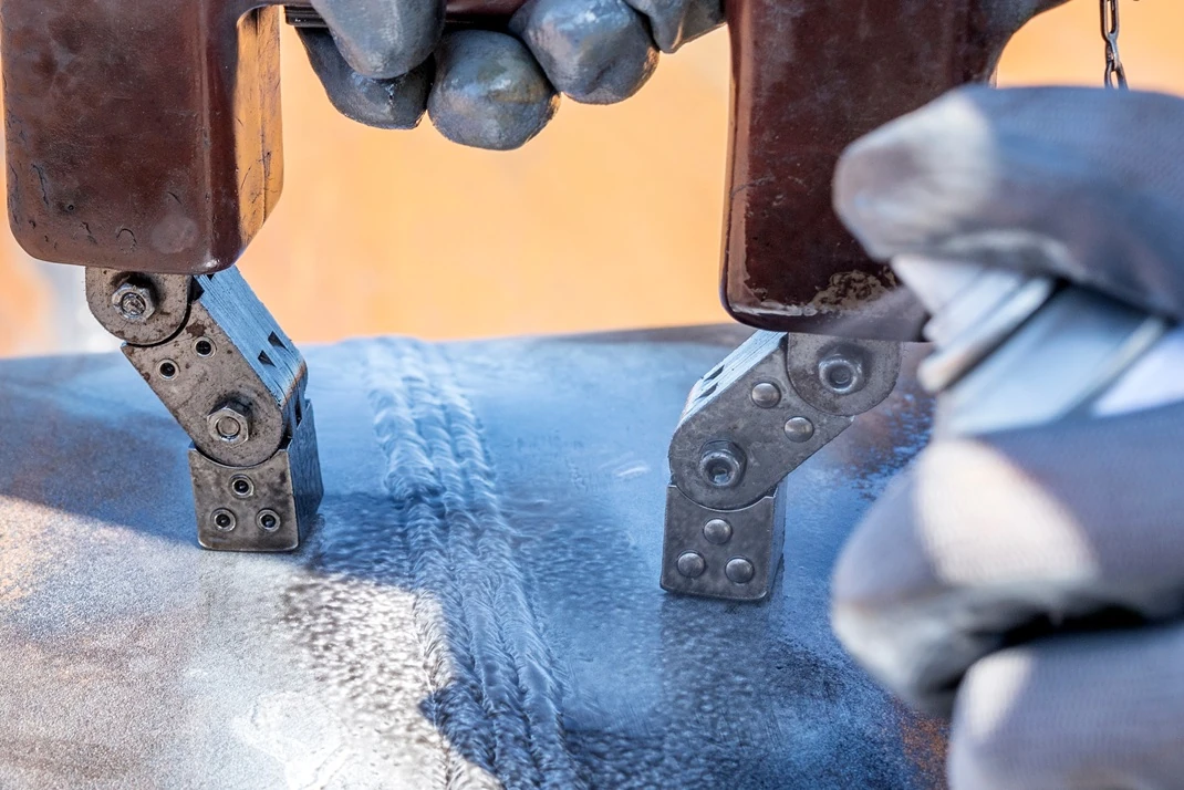
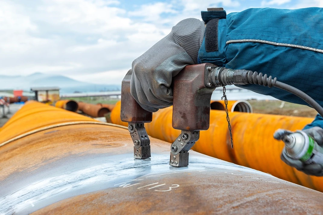
Where liquid couplant isn't practical, options such as EMAT (electromagnetic acoustic transducers) or dry-coupled probes exist, but they have their own limits. A good survey plan states what each location will be measured with, and why.
Where Thickness Testing Is Used
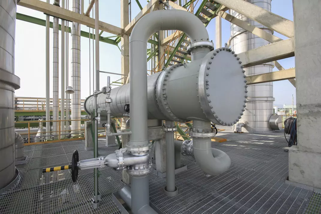
- Pressure vessels and heat exchanger shells: general and localised corrosion, especially at the bottom, liquid levels and nozzles.
- Pressure piping: elbows, tees, reducers, dead legs, injection points and the soil-to-air interface.
- Storage tanks: shell courses, roofs, nozzles and floor plates.
- Chutes, hoppers and wear liners: wear and erosion on mining and materials-handling plant.
- Structural members: section loss on steelwork exposed to weather, splash zones or process spills.
Insulated equipment is a special case. Readings need access through the insulation, and the worst corrosion is often under it. Our guide to corrosion under insulation covers how that is managed.
What a Thickness Survey Report Should Include
A thickness report you can trend from one survey to the next should state:
- The equipment and drawing, with each location identified.
- The nominal or previous thickness and the measured value: the minimum and, where a grid is used, the average.
- The instrument, probe, calibration block and technique, including whether readings were taken through coating.
- The surface temperature at the time of reading.
- Any locations that couldn't be measured, and why.
- Where mapping was used, the C-scan images with scale and position reference.
Where readings fall below the minimum required thickness, the next step is an engineering assessment, such as a fitness-for-service assessment, rather than an automatic repair or retirement decision.
APEC Inspection is based in Newcastle and provides ultrasonic testing, including thickness surveys and corrosion mapping, and phased array ultrasonic testing, as part of pressure vessel inspection and wider plant inspection. We are accredited by NATA to ISO/IEC 17025:2017, and our non-destructive testing is carried out by technicians certified to ISO 9712 through AINDT. To scope a survey, request a quote with the equipment, drawings and any previous thickness data you hold.