What Is Phased Array Ultrasonic Testing?
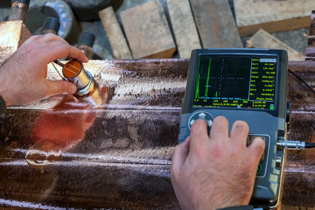
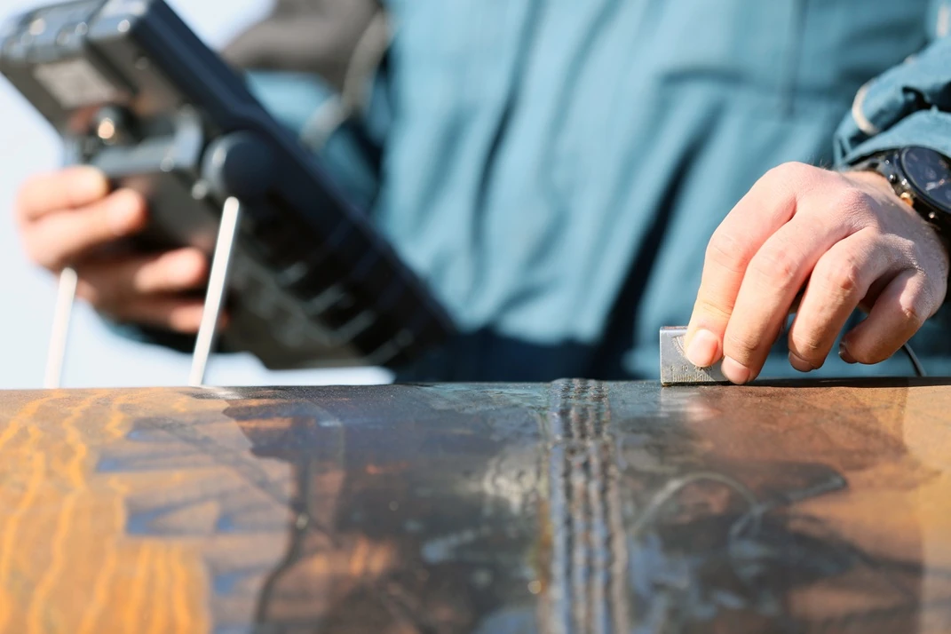
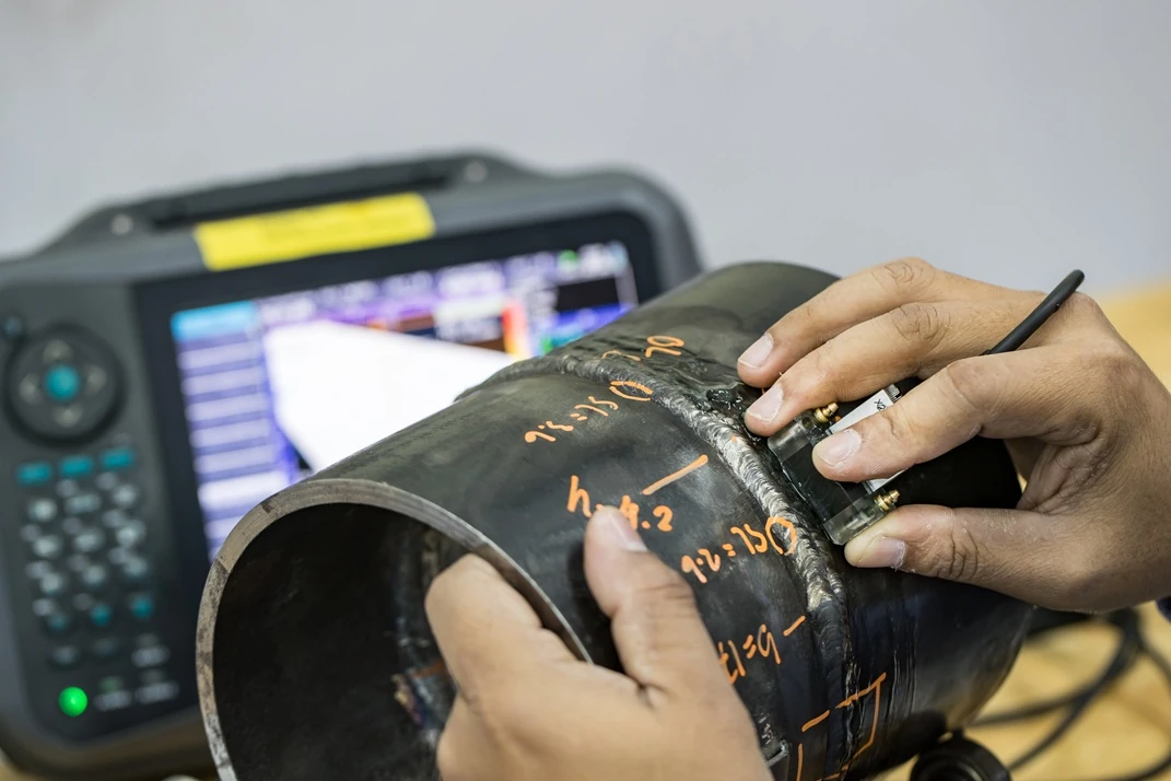
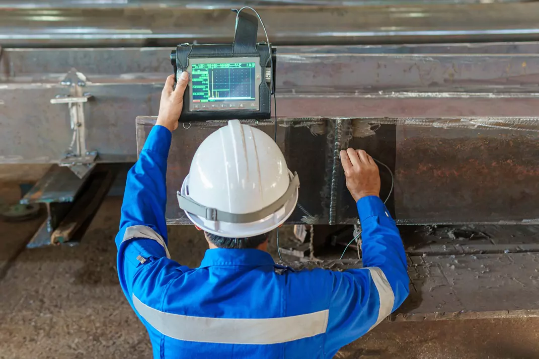
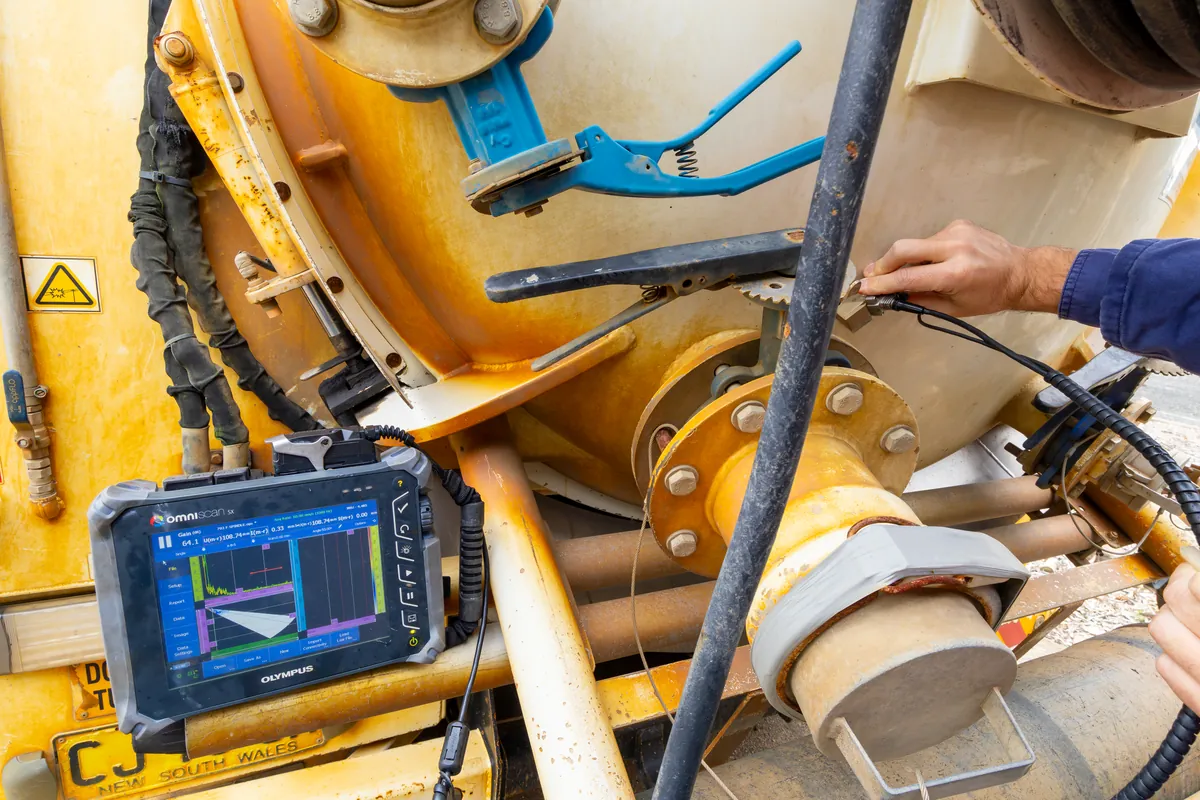
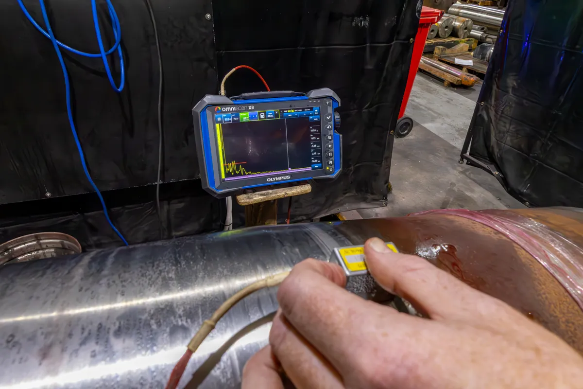
Phased array ultrasonic testing (PAUT) is an advanced form of ultrasonic testing. A conventional ultrasonic probe has a single element that sends sound into the material at one fixed angle. A phased array probe has many small elements, often 16, 32, 64 or more, in one housing. By firing those elements with carefully timed delays, the instrument can steer the sound beam through a range of angles and focus it at different depths, all electronically, without moving the probe.
The result is an image rather than a single trace. The technician sees a cross-section through the weld or component, with any reflectors such as cracks, lack of fusion or corrosion shown in position. This makes indications faster to find, easier to interpret and easier to record.
How PAUT Works
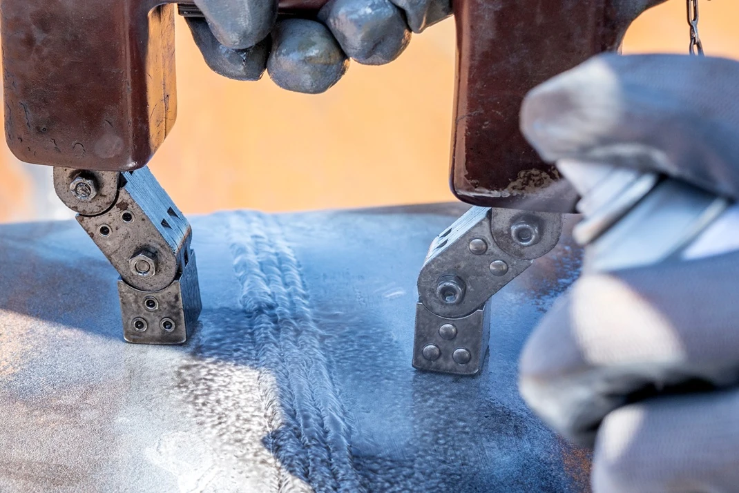
Each pattern of firing delays is called a focal law. The instrument cycles through hundreds of focal laws in a fraction of a second, building up the image as it goes. The probe is usually mounted on a wedge, which sets the starting angle and protects the elements.

PAUT data is shown in several standard views:
- A-scan: the basic ultrasonic trace of signal amplitude against time for one beam.
- S-scan (sectorial scan): a fan-shaped cross-section built from beams swept through a range of angles.
- B-scan: a side-on cross-section along the scan line.
- C-scan: a plan view, often colour-coded by depth or amplitude, as used for corrosion maps.
Scans can be manual, where the technician moves the probe and interprets in real time, or encoded, where an encoder records the probe position. Encoded scans store the complete data set, so it can be reviewed later, audited and compared with future inspections.
Before scanning, the setup is chosen and checked. Probe frequency, the number of active elements (the aperture) and element spacing (pitch) are selected to suit the material and thickness, and the system is calibrated for wedge delay, sound velocity and sensitivity, including time-corrected gain (TCG) so reflectors at different depths can be compared fairly.
PAUT Scan Types and Techniques
Sectorial scanning (S-scan) sweeps the beam through a range of angles from one probe position. It is the most common technique for weld inspection because one pass covers the weld volume from several angles, which improves the chance of finding flaws in any orientation.
Linear (electronic) scanning fires groups of elements in sequence along the probe at a fixed angle, moving the beam electronically. Linear scans at zero degrees are used for thickness and corrosion mapping, and angled linear scans are used on welds.
Compound scans combine sectorial and linear scanning. Separately, full matrix capture (FMC) with the total focusing method (TFM) records signals from every element pair and focuses at every point in the image. TFM gives very sharp images, which is useful for characterising and sizing cracks, but it needs capable equipment and careful setup.
PAUT is often paired with time of flight diffraction (TOFD), which is very good at measuring flaw height. Our guide to contact, immersion and TOFD ultrasonic techniques explains TOFD and the conventional techniques.
PAUT vs Conventional Ultrasonic Testing
| Conventional UT | Phased array UT | |
|---|---|---|
| Beam | One fixed angle per probe | Steered and focused electronically through many angles |
| Result | A-scan trace interpreted by the technician | Cross-sectional and plan-view images |
| Coverage | Several probes and passes to cover a weld | Often one or two passes with an S-scan |
| Records | Usually readings and notes | Full data set can be saved when the scan is encoded |
| Setup | Simple and quick | Needs a scan plan, focal laws and calibration |
| Best for | Spot checks, thickness readings, simple geometry | Welds, complex geometry, corrosion mapping, audited records |
Conventional UT is still the right choice for many jobs, such as spot thickness readings or a quick check on a simple weld. PAUT earns its extra setup time where coverage, imaging or a permanent record matters.
PAUT vs Radiography
PAUT is increasingly used where radiographic testing (RT) has traditionally been specified for welds. It involves no ionising radiation, so other work can continue nearby without exclusion zones. It is generally better than RT at finding planar flaws such as cracks and lack of fusion, and it measures the depth of a flaw as well as its length.
RT still has strengths. It gives a direct picture of volumetric flaws such as porosity, and it is long established in many codes. Whether PAUT can replace RT on a job depends on the code or specification and the client's acceptance. Our article on phased array weld inspection compares the two methods for welds in more detail.
Advantages and Limitations of PAUT
Advantages: faster coverage of welds and large areas, images that are easier to interpret and explain, better detection of planar flaws at different orientations, flaw sizing, permanent encoded records, and no radiation hazard.
Limitations: PAUT needs a well-prepared scan plan, careful calibration and an experienced, certified operator, because results depend heavily on setup. Coarse-grained materials, such as austenitic stainless steel welds and some castings, scatter sound and are harder to inspect. Surface condition, access and geometry all affect coverage, and for a handful of spot thickness readings, a simple thickness gauge is quicker and cheaper.
How deep PAUT can inspect depends on the material, the probe frequency and the geometry. Lower frequencies penetrate further, and higher frequencies give finer resolution. The scan plan sets these for each job.
Where PAUT Is Used
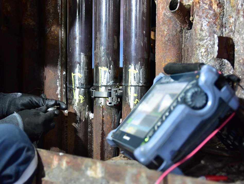
- Weld inspection on pressure vessels, pipework, structural steel and storage tanks, both during fabrication and in service. See phased array weld inspection.
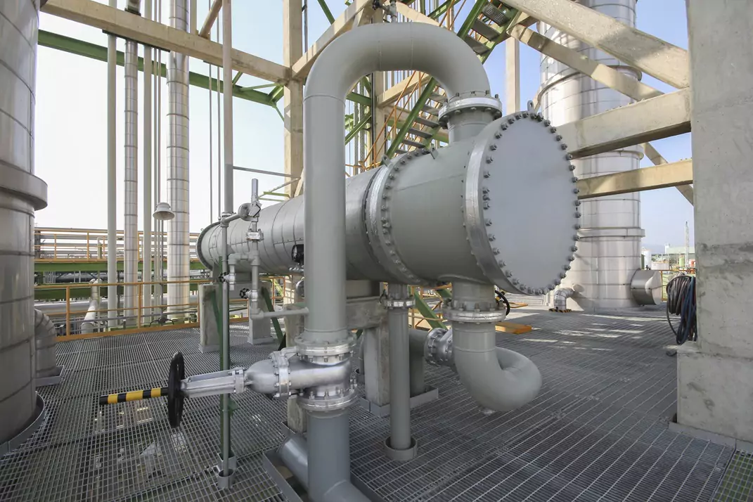
- Corrosion mapping of vessel shells, pipe and tank walls, producing a C-scan map of remaining thickness. See our guide to ultrasonic thickness testing and corrosion mapping.
- Nozzles and complex geometry, where steering the beam reaches areas a fixed-angle probe cannot.
- Crack detection and sizing in service, for example at weld toes and attachments subject to fatigue.
- Storage tanks, for shell, nozzle and annular plate welds and for corrosion mapping of shell plates during an API 653 tank inspection. Tank floors are usually screened with other methods first; see MFL vs ultrasonic tank floor inspection.
- Forgings, castings and components, where internal soundness needs to be confirmed.
For pressure equipment, PAUT supports the in-service inspection required under AS/NZS 3788 by measuring wall loss and checking welds without taking the vessel apart.
Standards and Personnel
The standard that applies depends on the job. Welds are often inspected to the ultrasonic testing standard named in the fabrication code, such as AS 2207 for welds in carbon and low-alloy steel. ISO 13588 covers the use of automated phased array technology for testing welds, and ASME Section V includes phased array requirements for work to ASME codes. The acceptance criteria come from the design or fabrication standard, or the project specification. Standards are revised, and requirements change between editions. Always check which edition your contract, drawing or regulator cites before relying on any requirement.
Personnel should hold ISO 9712 certification in ultrasonic testing, administered in Australia through AINDT, with training and experience in phased array. Ask your provider for evidence of both.
Planning a PAUT Inspection
A good PAUT result starts with good information. Before the job, provide:
- Drawings showing the weld or area, material, thickness and joint preparation.
- The code, standard or specification, and the acceptance criteria.
- Access and surface condition, including any coatings, insulation or temperature limits.
- Whether you need an encoded record for future comparison.
With that, the technician prepares a scan plan showing probe positions, angles and coverage. After the inspection you receive a report describing the method, the coverage achieved, any indications with their position and size, and an assessment against the acceptance criteria.
PAUT at APEC Inspection
APEC Inspection provides phased array ultrasonic testing for welds, corrosion mapping and components, in our workshop and on site across New South Wales and interstate. PAUT sits alongside our conventional ultrasonic testing, magnetic particle inspection and pressure vessel inspection, so the right method can be used for each part of a job.
We are accredited by NATA to ISO/IEC 17025:2017, and our non-destructive testing is carried out by technicians certified to ISO 9712 through AINDT. To arrange PAUT, request a quote and include the drawings, material, thickness and the standard that applies.