Ultrasonic inspection - Compare contact, immersion and TOFD
Choose the right ultrasonic testing methods. Practical probe selection, couplants and standards.
About Contact UsPublished on: 10 September 2025 | Estimated reading time: 13 minutes
What is Ultrasonic inspection — What it is, why it matters and where to use it
Ultrasonic inspection is a volumetric non‑destructive testing (NDT) method that uses high‑frequency sound to detect internal defects, size flaws and measure thickness without damaging the part.
Why it matters:
- Volumetric capability — finds internal cracks, voids, delaminations and thinning that surface methods cannot.
- Quantitative results — time‑of‑flight and imaging let you locate and size defects for fitness‑for‑service decisions.
- Safe and adaptable — no ionising radiation; methods range from portable contact gauges to automated immersion and mechanised TOFD/PAUT systems.
- Cost effective — in many Australian fabrication programmes UT replaces radiography for faster, recordable inspections.
Where to use it:
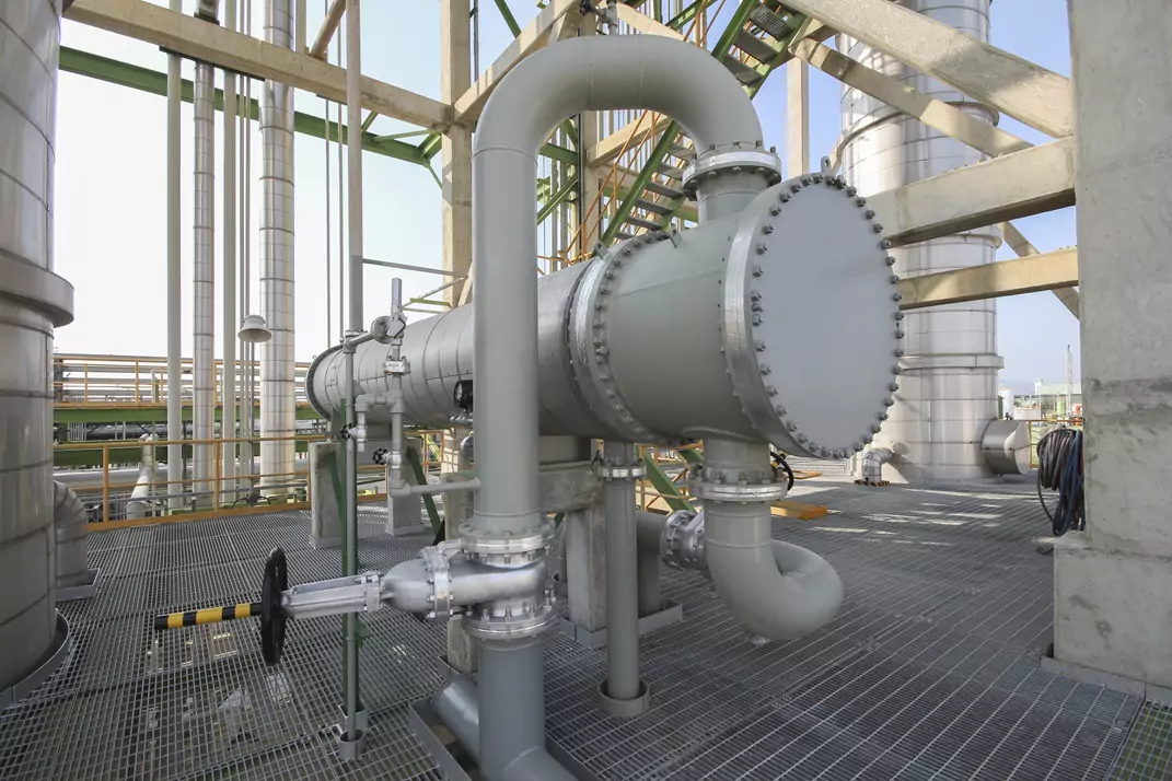
- Oil & gas pipeline girth welds, spools and in‑service corrosion mapping across NSW, QLD and WA sites.
- Power generation components, steam boilers and pressure vessels in thermal and emerging hydrogen plants.
- Aerospace and composites in controlled laboratory settings (immersion PAUT/TFM).
- Mining and heavy manufacturing for castings, forgings and critical machine components.
Quick takeaway: choose ultrasonic inspection whenever you need internal detection, reliable sizing and a record of the inspection outcome.
Source: APEC Ultrasonic Inspection service overview — Ultrasonic Inspection
Ultrasonic inspection techniques — Short primer on UT principles
Ultrasonic inspection techniques depend on how sound waves travel, reflect and diffract inside materials. A basic grasp of pulse‑echo, through‑transmission and diffraction principles helps you choose the right ultrasonic testing methods for a given part or defect type.
Pulse‑echo (A‑scan, B‑scan, C‑scan)
- Single transducer sends a short pulse and receives echoes from interfaces (defects, back wall).
- Time‑of‑flight → depth. Amplitude → reflector size/orientation (with caveats).
- Displays: A‑scan for signal, B‑scan for cross‑section, C‑scan for plan view mapping.
Through‑transmission (pitch‑catch)
- Separate transmitter and receiver on opposite faces. Loss of transmitted energy indicates flaws or high attenuation.
- Common in composites and bond testing where back wall echoes are weak.
Diffraction & TOFD principle
- Diffraction picks up energy from crack tips — TOFD uses time‑of‑flight of diffracted arrivals for accurate depth sizing.
- Less dependent on reflector amplitude than pulse‑echo.
Wave modes & conversions
- Longitudinal waves for thickness/back wall checks.
- Shear (angle) waves for weld inspection and crack orientation detection.
- Surface (Rayleigh) and guided waves for long‑range corrosion screening.
Attenuation, frequency trade‑offs & material effects
- Higher frequency → better resolution; higher attenuation in coarse‑grained materials (castings, austenitic welds).
- Typical industrial frequencies: 0.5–15 MHz depending on material and required resolution.
Related terms: phased array (PAUT), FMC/TFM, beam steering, time‑of‑flight, ultrasonic testing methods.
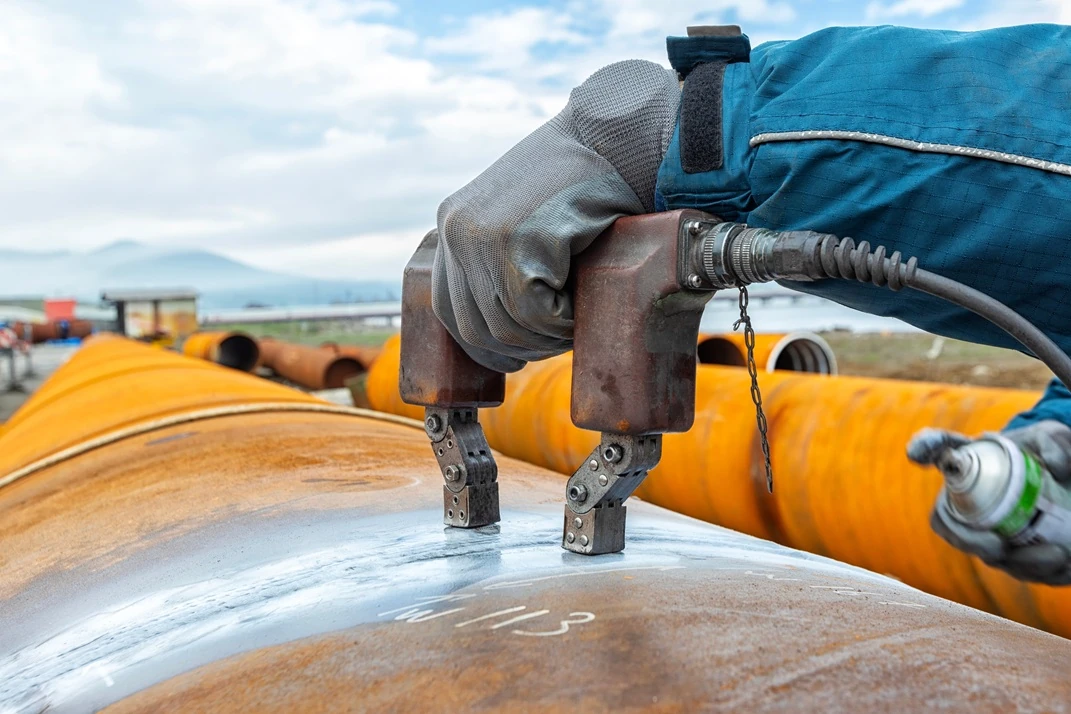
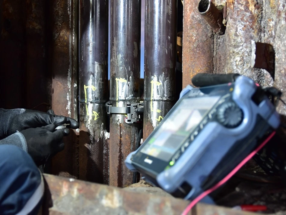
Contact ultrasonic testing — Contact (dry) method, pros & cons
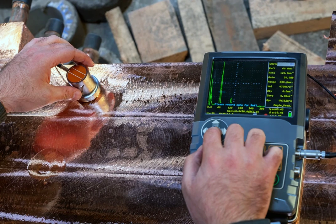
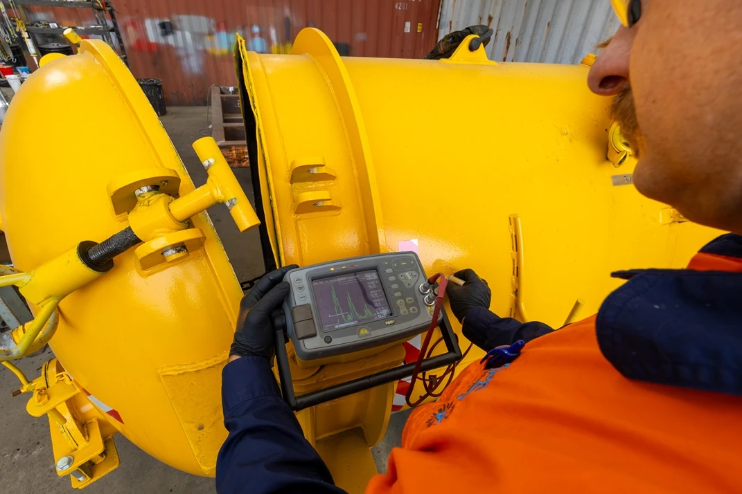
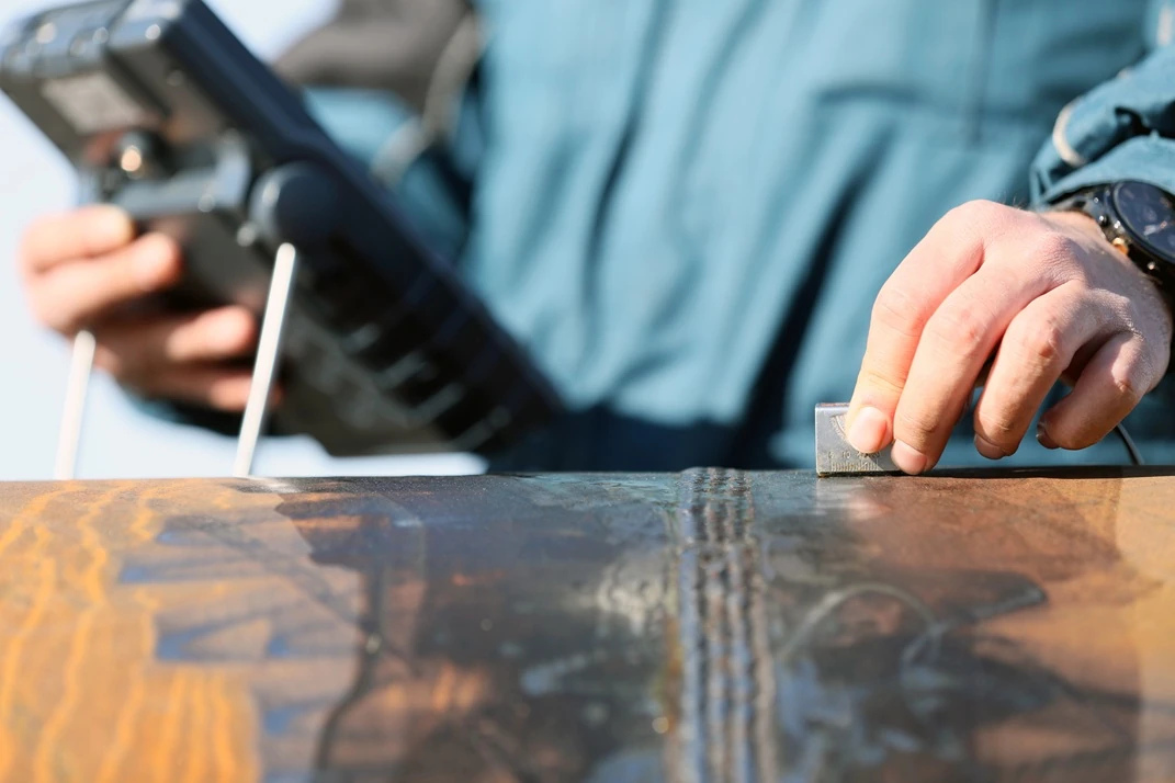
Contact ultrasonic testing, often called contact or dry UT, places a probe directly on the cleaned surface with a thin film of couplant to transmit and receive sound pulses. It’s the go‑to portable method for in‑service thickness surveys, spot weld inspection and shop‑floor checks because it’s fast, flexible and works on large fixed assemblies. Be aware it depends on good surface coupling, skilled operators and can have a near‑surface dead zone that limits detection of very shallow flaws.
How contact ultrasonic testing works
- Probe placed directly on the component with a thin layer of couplant (gel, oil) to remove air gap.
- Wedges produce refracted shear waves for angle beams; straight‑beam probes for thickness checks.
- Used manually, with wheel/encoder attachments, or mechanised scanners for repeatability.
Pros (why use contact UT)
- Portable and fast — ideal for on‑site, in‑service thickness surveys and spot weld checks.
- Flexible — angle beam, straight beam and phased array variants adapt to many geometries.
- Lower setup cost than immersion; works on large fixed assemblies without disassembly.
Cons (limitations to consider)
- Coupling reliant — paint, rust, scale and surface roughness degrade signal quality.
- Near‑surface dead zone for some probes; small shallow defects may be missed.
- Operator skill determines probability of detection (POD) and sizing accuracy.
- Complex geometry may require custom wedges or fixtures.
Typical uses in Australia
- Plant pipework corrosion surveys and tank inspections.
- Field weld inspections in fabrication yards and construction sites.
- Shop floor QA for forgings and large castings where portability matters.
Typical probe & frequency guidance (contact)
- Thickness/corrosion: 2–5 MHz straight beam for penetration; 5–10 MHz for thin plate resolution.
- Welds: 2.25–5 MHz angle beam (45°, 60°, 70° wedges common).
- Phased array: 1–5 MHz arrays common for welds and thicker sections (vendor guidance for element count and pitch).
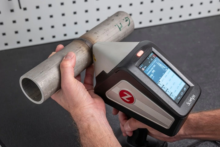
Immersion ultrasonic testing — How it works, pros & cons
Immersion ultrasonic testing uses water as a stable coupling medium, with the part submerged or scanned using a water‑filled shoe to deliver highly consistent, repeatable signals. Because immersion enables higher frequencies and mechanised gantry or robotic scanning, it supports PAUT, FMC/TFM and high‑resolution C‑scan imaging for ultrasonic inspection of composites, aerospace panels, turbine blades and detailed casting analysis. This method is primarily a shop or laboratory technique in Australia—excellent for repeatable QA but impractical for large in‑service items due to tank logistics, water treatment and drying requirements. Choose immersion ultrasonic testing when you need the best resolution and documented C‑scan maps; for field or in‑service work, contact UT or mechanised PAUT are generally more practical.
How immersion ultrasonic testing works
- Part and probe are immersed in water or scanned with a water‑filled shoe; water is the coupling medium.
- Mechanised gantry or robot moves the probe for repeatable, encoded scans.
- Commonly used with PAUT and FMC/TFM for high‑resolution imaging.
Pros (why use immersion)
- Stable, uniform coupling produces consistent signals — ideal for repeatable C‑scans and automation.
- Enables higher frequencies (5–15 MHz) for fine defect detection in composites and small components.
- Excellent for aerospace panels, turbine blades, and detailed casting analysis.
Cons (practical limits)
- Not practical for in‑service field inspections without disassembly.
- Requires tanks, water treatment and drying procedures — higher logistics cost.
- Less portable; best suited to shop, depot or laboratory environments.
Typical uses in Australia
- Aerospace composite testing and engine component QA in metropolitan labs (Sydney, Melbourne).
- Railway wheel/axle bench testing and detailed casting scans in workshops.
- R&D and validation using FMC/TFM for ultimate resolution.
Probe / frequency guidance (immersion)
- Use 5–15 MHz for high resolution; 10–15 MHz common for composite delamination work.
- Small diameter broadband probes deliver improved lateral resolution and near‑surface response.
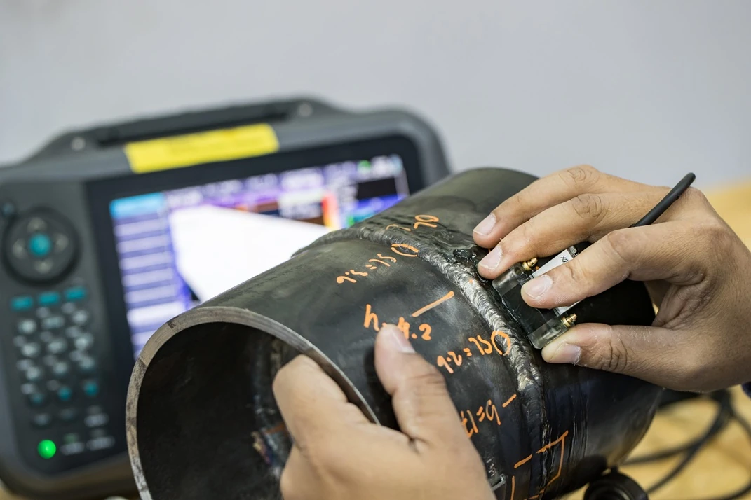
TOFD ultrasonic — Principle, strengths and limits
How TOFD ultrasonic works
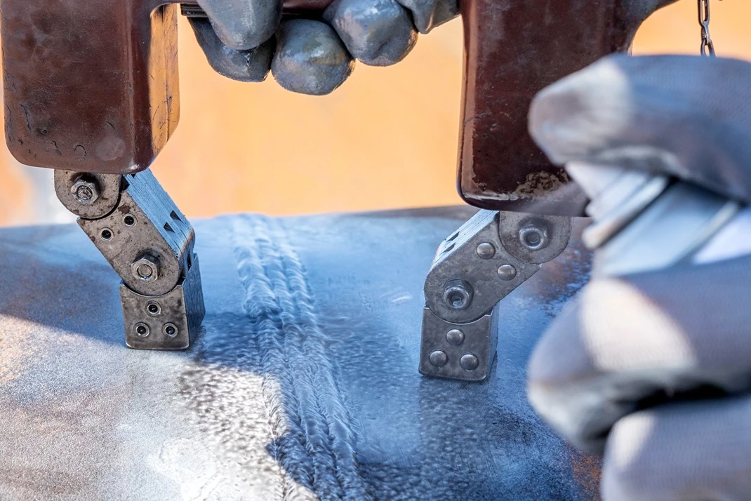
TOFD (time‑of‑flight diffraction) is an ultrasonic technique that detects sound diffracted from crack tips instead of relying on reflection amplitude. It gives very accurate depth and tip‑to‑tip sizing and has a high probability of detection for planar defects, so it’s commonly used on pipeline girth welds and pressure‑class fabrications in Australia. TOFD does have limits: a near‑surface dead zone can hide very shallow flaws, and diffracted signals are often low amplitude and can be masked by noise or coarse grain scatter. For full coverage and the best confidence, TOFD is usually paired with angle‑beam or PAUT to cover near‑surface and backwall zones.
- Two probes placed across the weld in a through‑transmission geometry (transmitter + receiver).
- TOFD records the lateral wave, back wall and diffracted waves from crack tips; depth is derived from time‑of‑flight of diffracted arrivals.
- TOFD provides accurate tip‑to‑tip depth sizing rather than relying on reflection amplitude.
Strengths of TOFD ultrasonic
- High probability of detection (POD) for planar defects such as cracks and lack of fusion.
- Accurate depth sizing that is relatively independent of reflector amplitude.
- Fast when mechanised; stores recordable data for re‑analysis and trending.
Limitations of TOFD
- Poor near‑surface resolution — a near‑surface "dead zone" may miss very shallow defects.
- Diffracted signals can be low amplitude and masked by noise in coarse‑grained materials.
- TOFD alone can miss small side‑drilled or orientation‑specific reflectors — combine with PAUT or angle beam for full coverage.
Practical TOFD settings (industry practice)
- Probe centre spacing (PCS): chosen by wall thickness — typical PCS ~50–120 mm.
- Probe frequencies: 2.5–10 MHz broadband are common for welds.
- Scan step: 1–3 mm for high‑resolution weld mapping; sampling ≥1 sample/mm recommended for reliable imaging.
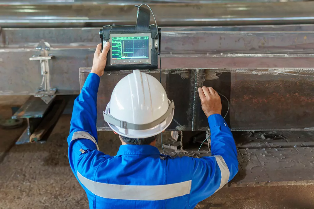
Ultrasonic Flaw Detection — Applications and industries
Pipelines and welds
- Pipeline girth weld inspection: mechanised TOFD + PAUT used widely in Australian onshore construction to replace radiography where the client/spec allows.
- Fabrication QA: PAUT sector scans for defect detection + TOFD for depth sizing.
Castings and forgings
- Immersion PAUT/TFM for lab‑grade imaging of small casting defects.
- Contact UT for shop floor screening of large castings and forgings.
Corrosion mapping and thickness measurement
- Contact thickness gauges for spot checks and trending in field assets.
- PAUT wheel probes and mechanised scanning for rapid, recordable corrosion mapping in plant pipework.
Composites and aerospace
- Immersion PAUT with FMC/TFM for delaminations, bond defects and porosity — required for certification of aerospace components.
Heavy industry and rail
- Axles, wheels and rails: PAUT combined with MPI or surface methods to cover internal and near‑surface flaws.
Decision heuristics:
- Need depth sizing and high POD → TOFD + PAUT.
- Field in‑service thickness checks → contact UT (thickness gauge or spot PAUT).
- Lab‑grade, repeatable QA → immersion PAUT / TFM.
Source: APEC services and industry coverage — Ultrasonic Inspection
Ultrasonic inspection techniques — Probe selection, couplants, surface prep and common setup mistakes
Probe selection rules
- Frequency: thin sections → higher frequency (5–15 MHz) for resolution; thick or coarse‑grained → lower frequency (0.5–5 MHz) for penetration.
- Probe type: straight beam for thickness/back wall; angle beam for welds; phased array for steering/focusing; small broadband probes for TOFD.
- Size: small crystals improve near‑surface resolution; larger crystals increase penetration.
- Wedges: choose wedge material and angle to achieve the correct refracted angle (Snell’s law applies).
Couplants
- Water for immersion; oils, gels and water‑based coupling gel for contact UT; specialised high‑temperature couplants for hot work.
- Avoid halide or corrosive additives on stainless and nickel alloys; use de‑ionised water in sensitive lab work if specified.
- Ensure adequate couplant film — poor coupling causes signal loss and noise.
Surface preparation
- Remove loose scale, heavy rust and thick paint where the procedure requires it; light paint may be acceptable for coarse surveys but reduces sensitivity.
- Ensure wedge faces and probe lenses are clean and undamaged.
- For TOFD and mechanised scans, maintain consistent probe spacing and an encoded scanner track for repeatability.
Calibration essentials
- Use representative calibration blocks: FBH/SDH for amplitude and sizing; IIW blocks for angle beam checks.
- Set DAC/TCG and verify amplitude linearity across depth.
- Verify sound velocity for the specific material and compensate for temperature differences.
- TOFD: calibrate PCS, lateral wave zero and back wall timing before scanning.
Common setup mistakes
- Poor / inconsistent coupling — always check back wall and lateral wave echoes on a known area first.
- Wrong probe/wedge angle or refracted angle selection — verify wedge angle and sound velocity.
- Incorrect frequency choice — too high causes attenuation; too low loses resolution.
- Wrong gain/TCG settings leading to missed or false calls — follow procedure and primary reference reflectors.
- Neglecting temperature compensation — sound velocity varies with temperature and affects depth readings.
- Not saving raw A/B/C scan data for traceability and audit.
Quick operator checklist before scanning:
- Confirm procedure and acceptance criteria.
- Inspect probe, wedge and cable for damage.
- Calibrate on representative block and record DAC/TCG.
- Verify coupling and back wall echo; set gates and timebase; start conservative scan speed for review.
Ultrasonic testing methods — When to combine methods and standards to reference
Why combine methods
- Complementary strengths: TOFD for depth sizing; PAUT/angle beam for near‑surface/back wall coverage and defect morphology.
- Redundancy increases confidence and reduces false negatives on critical components.
- Mechanised combined scans (TOFD + PAUT) deliver both detection and sizing in a single pass and generate recordable data for audits.
Common combinations
- TOFD + PAUT: standard for pipeline girth welds and pressure equipment.
- PAUT + TFM/FMC: for the highest resolution imaging in composites and forgings.
- Through‑transmission + pulse‑echo: useful on laminates and certain bonded structures.
Standards and codes (Australian context)
- ASME Section V — NDT procedure and instrument guidance (where referenced by purchaser).
- ISO 17640 — Ultrasonic testing of welds — techniques and assessment.
- ASTM E2373 — Standard practice for TOFD.
- ASTM E1961 — Mechanised UT of girth welds (zonal discrimination).
- ISO 9712 / AINDT — Personnel qualifications; NATA accreditation for labs in Australia.
- Always follow the purchaser’s specification and local regulatory rules (e.g., SafeWork NSW) for pressure equipment.
Example workflow (pipeline girth welds): mechanised TOFD strip + PAUT sector scan in a single pass; calibrate on representative coupon; save C‑scans and TOFD records for audit.
Practical decision flow — Choosing the right UT method
Quick decision questions
- Do you need internal detection or surface only? → Ultrasonic inspection for internal; MPI/PT for surface.
- Is accurate depth sizing required? → Use TOFD plus PAUT.
- Is the job in the field or the lab? → Field → contact UT. Lab → immersion UT with PAUT/TFM.
- Is the material coarse‑grained or highly attenuative? → Lower frequency or different method (immersion or RT) may be needed.
Method cheat sheet
- Contact UT: portability, thickness surveys, field weld checks.
- Immersion UT: high repeatability, high resolution imaging, composites and small parts.
- TOFD ultrasonic: accurate depth sizing of planar defects, mechanised weld inspection; combine with PAUT for full coverage.
Example Australian choices:
- Onshore pipeline construction: mechanised TOFD + PAUT (where code permits replacement of RT).
- Mining workshop: contact UT for incoming forgings and regular thickness surveys.
- Aerospace supplier: immersion PAUT + TFM for panel certification and bondline inspection.
Reporting, traceability and operator competence
Reporting essentials
- Save raw A‑scan/B‑scan/C‑scan and TOFD records; include calibration block traceability.
- Record probe and wedge serial numbers, instrument settings, sound velocity used and DAC/TCG curves.
- Annotate defects with coordinates, depth, length and assessment against acceptance criteria.
Personnel & accreditation
- Use technicians certified to ISO 9712 / AINDT for formal inspections; labs should be NATA accredited when required.
- Maintain currency of qualifications and instrument competency checks per ASNT/ISO guidance.
Australian legal & safety context
- Follow SafeWork NSW and state regulators for pressure equipment inspections and reporting requirements.
- Align procedures with client spec and the governing standard for the asset (ASME, ISO, API as applicable).
Source: APEC accreditation and qualifications — About APEC Inspection
Summary
Decision line: use contact ultrasonic inspection for portable field tasks and spot thickness checks; use immersion ultrasonic testing for lab‑grade, repeatable high‑resolution work; use TOFD ultrasonic when accurate depth sizing of planar defects is critical — combine TOFD + PAUT to cover both detection and sizing for high‑assurance inspections.
Always calibrate on representative blocks, follow the governing standard or purchaser specification, save raw data for traceability and use certified operators for regulated inspections in Australia.
For project advice, downloadable method selection matrices or asset‑specific recommendations, contact APEC Inspect.
Source: APEC Ultrasonic Inspection services — Ultrasonic Inspection | Phased Array Ultrasonic Testing
Frequently Asked Questions About Ultrasonic inspection
1. What is ultrasonic inspection and how does it work?
+Ultrasonic inspection uses high‑frequency sound pulses transmitted into a part. Echoes from interfaces and defects are recorded; time‑of‑flight gives depth and amplitude/shape provide defect information.
2. When should I use contact UT versus immersion UT?
+Use contact UT for portable field surveys and thickness checks. Use immersion UT for laboratory or depot work demanding high repeatability and high resolution, such as aerospace composite inspection.
3. What is TOFD ultrasonic best used for?
+TOFD ultrasonic is best for accurate depth sizing of planar defects (cracks, lack of fusion). It is commonly used mechanised on pipeline girth welds and pressure vessel fabrication.
4. Can TOFD detect very shallow defects?
+TOFD has a near‑surface dead zone and may miss very shallow defects. Combine TOFD with PAUT or angle beam pulse‑echo to cover near‑surface regions.
5. How do I choose probe frequency for ultrasonic flaw detection?
+Balance resolution versus penetration: higher frequency (5–15 MHz) for thin parts and fine flaws; lower frequency (0.5–5 MHz) for thick or coarse‑grained materials to reduce attenuation.
6. What couplant should I use for contact UT?
+Typical couplants are water, oils or water‑based gels. Choose a couplant compatible with the material (avoid halide contaminants on stainless). For hot surfaces use specialised high‑temperature couplants.
7. Which standards should I reference for ultrasonic testing methods?
+Useful standards include ISO 17640 (weld UT), ASTM E2373 (TOFD), ASME Section V (procedures), ASTM E1961 (mechanised UT) and ISO 9712/AINDT for personnel qualification. Follow purchaser specs and local regulations.
8. How should I record and report UT results for traceability?
+Save raw A‑scans/B‑scans/C‑scans, calibration block traceability, probe and wedge serials, instrument settings, velocity and DAC/TCG. Annotate defect coordinates and sizing against acceptance criteria.
9. What are common mistakes that reduce UT effectiveness?
+Common errors: poor coupling, wrong probe frequency/angle, incorrect velocity settings, inadequate calibration, ignoring temperature compensation and not saving records for audit.
10. Do I need certified operators for ultrasonic inspection in Australia?
+Yes. For formal inspections use ISO 9712 / AINDT certified personnel and NATA‑accredited labs where required. Certification ensures consistent, defendable results for regulated assets.
Comprehensive NDT Solutions: The APEC Inspect Advantage
APEC Inspect offers a complete range of NDT and inspection services, each complementing the others to provide comprehensive asset integrity solutions. Our Newcastle-based team brings decades of combined experience across all major industries in New South Wales and beyond.
Why Choose APEC Inspect?
- Comprehensive Expertise: From basic visual inspection to advanced PAUT, we offer the full spectrum of NDT services.
- Australian Standards: All our work complies with relevant Australian and international standards.
- Certified Personnel: Our team maintains current certification across all inspection methods.
- Modern Equipment: We continuously invest in the latest NDT technology.
- Customer Focus: We understand that each client's needs are unique and tailor our services accordingly.
Industry Coverage
We serve multiple sectors including:
- Mining and Resources
- Manufacturing
- Hydrogen Plants
- Power Generation
- Oil and Gas
- Marine
- Construction
- Infrastructure
Contact Us
For more information about any of our services or to discuss your specific inspection needs, contact our Newcastle office. Our technical team is ready to develop a comprehensive inspection program tailored to your requirements.
Recent Posts


© apecinspect.com.au. All Rights Reserved. Designed by Peritus Digital