Why Tank Floors Fail First
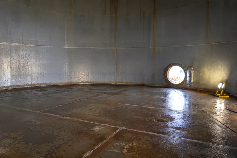
Ask anyone who has spent time around bulk storage and they will tell you the same thing: tanks deteriorate from the bottom up. It is not that the floor is built worse than the rest of the tank. It is that the floor lives in the worst conditions and is the hardest part to see.
Water and sediment separate out of most stored products and settle. That water sits on the plate, often for years, and creates precisely the conditions corrosion needs. At the same time the underside of the floor is in contact with the foundation, where moisture, poor drainage and failed cathodic protection can eat the plate from below. Neither of those is visible during an external inspection, and neither shows up in a routine walk-around.
By the time floor corrosion announces itself as a leak, the problem is well advanced and the consequences are environmental as well as commercial. This is why an internal inspection concentrates on the floor, and why the floor gets the most technically involved examination of anything in the tank.
How Magnetic Flux Leakage Works
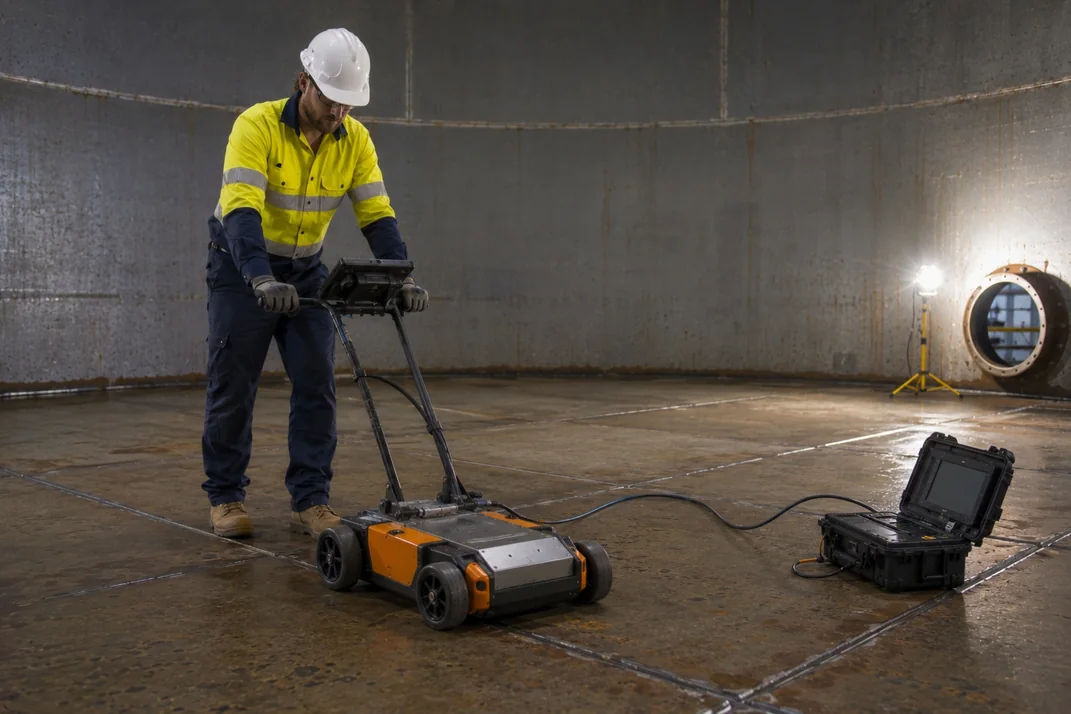
Magnetic flux leakage, almost always shortened to MFL, is the workhorse of tank floor scanning. The principle is straightforward. A powerful magnet in the scanner head saturates the steel plate with magnetic flux. Where the plate is sound, that flux stays inside the steel. Where metal is missing, whether from a pit on the top surface or corrosion on the underside, the flux is forced out of the plate and leaks into the air above it. Sensors in the scanner detect that leakage and record it.
The advantage is speed. An operator can walk a scanner across a floor and cover a large area quickly, producing a map of where metal loss is concentrated. On a tank floor of any size that matters enormously, because the alternative, taking manual readings across the whole floor on a grid, is impractical within a shutdown window.
MFL is a screening method. It tells you where to look, and it is very good at it.
Where MFL Reaches Its Limits
MFL has real constraints, and understanding them is what separates a competent floor inspection from a misleading one.
It is a comparative technique rather than an absolute one. The signal indicates that metal is missing and roughly how much, but it does not deliver a precise remaining-thickness figure. It also cannot reliably distinguish top-surface loss from underside loss on its own, which matters because the two have different causes and different remedies.
Performance falls away as plate thickness increases, because saturating thicker steel is harder. Coatings and linings add lift-off between the sensor and the plate, which reduces sensitivity. And the scanner cannot reach everywhere: the areas immediately adjacent to welds, around sump edges, under pipework and at the shell-to-floor junction are all difficult or impossible to cover with a standard scanner head, which is why those areas are handled separately.
None of this makes MFL unreliable. It makes it the first half of the job.
How Ultrasonic Thickness Testing Works
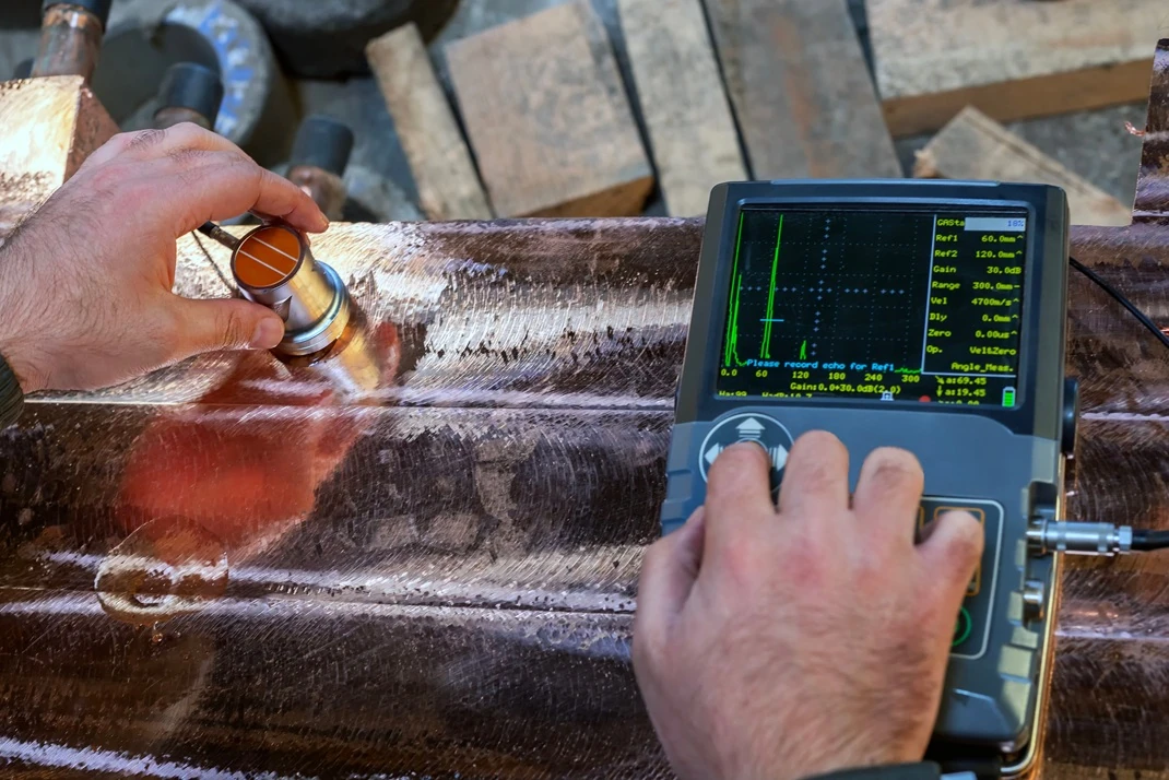
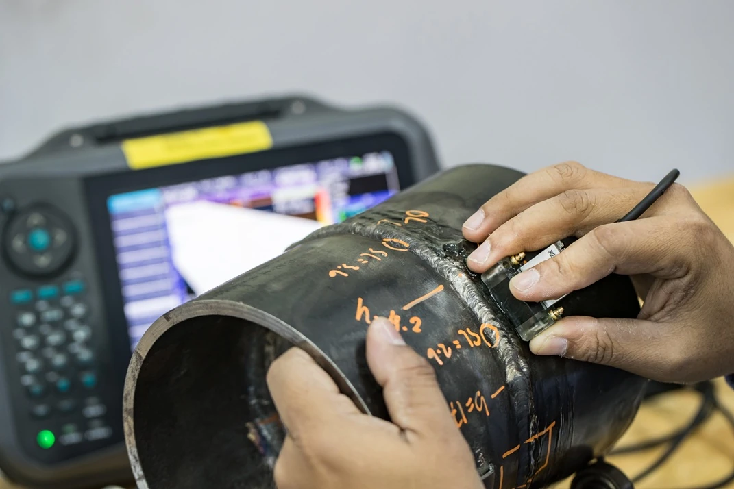
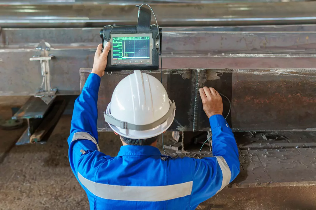
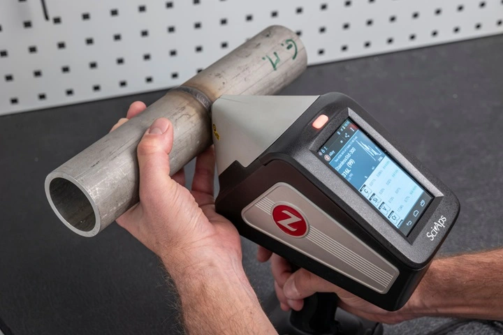
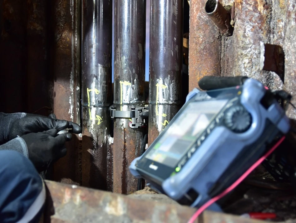
Ultrasonic testing works on a completely different principle. A probe sends a high-frequency sound pulse into the steel. The pulse travels through the plate, reflects off the back wall, and returns. Because the speed of sound in steel is known, the time taken gives the thickness directly.
The output is an absolute number in millimetres, not an indication. That is exactly what the evaluation step of an inspection needs, because minimum required thickness, corrosion rate and remaining life are all calculations that require real measurements.
The trade-off is coverage. A UT reading measures one small spot. Building a picture of a whole floor from UT alone would take an unreasonable amount of time and would still risk missing a pit between reading points.
Why Both Are Used Together
Set the two methods side by side and the logic becomes obvious. MFL covers ground quickly but gives indications rather than measurements. UT gives precise measurements but only where the probe is placed.
Used together they complement each other exactly. MFL scans the floor and produces a map of where metal loss is concentrated. The inspector then takes UT readings at the locations MFL has flagged, converting indications into measured thickness figures that can be used in the code calculations. Additional UT readings are taken at defined grid positions to establish general condition and to give the next inspection something to compare against.
Anyone offering a floor inspection using only one of the two is either going to miss things or take far too long. The combination is the standard approach for good reason.
Vacuum Box Testing: Proving the Welds
Thickness is only part of the question. The floor also has to be leak-tight, and the welds joining the floor plates are the most likely place for that to fail.
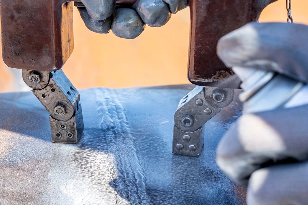
Vacuum box testing addresses it directly. A transparent box with a sealing gasket is placed over a weld seam that has been coated with a soap solution. Air is drawn out of the box to create a partial vacuum. If there is a through-thickness defect in the weld, air is pulled through it from beneath and forms visible bubbles in the solution.
It is simple, it is genuinely conclusive for through-thickness defects, and it does not require the tank to be filled. Along with MFL and UT it forms the third element of a complete floor assessment.
Reading the Floor Map
The output of a floor inspection should not be a pile of raw readings. It should be a map, and a set of conclusions drawn from it.
A good report shows where metal loss was found, how severe it is, and whether it originated on the top surface or the underside. That distinction drives the remedy: top-surface loss usually points to water and sediment sitting in the tank and may be addressed by operational changes and lining, while underside loss points to the foundation, drainage or cathodic protection and needs a different response entirely.
Those figures then feed the assessment. Measured thickness against minimum required thickness gives the margin. The change since the last inspection gives the corrosion rate. Together they set remaining life and the date the next internal inspection falls due, which is the output an owner can actually plan a budget around. This process is covered in more detail on our storage tank inspection services page.
When a Floor Fails Assessment
If measured thickness has fallen below the minimum the code allows, doing nothing is not among the options. There are generally three paths.
The tank can be repaired, which for floors usually means patch plates over affected areas or replacing whole plates. Where deterioration is widespread, a new floor can be laid over the existing one, though that carries its own considerations and has to be assessed properly rather than assumed.
The tank can be derated so it operates at a lower level, reducing stress on affected components. This buys time but does not solve the underlying problem.
Or the interval can be shortened and the tank monitored more frequently, which is only defensible when the margin remaining genuinely supports it.
Which path makes sense depends on the numbers, the tank's role and what else is planned for the site. If you have a shutdown coming up and want to talk through scope, request a quote and we can work through it with you.