A Thermal Image Is Not Automatically a Measurement
An infrared camera produces a clear image quickly, which makes thermography look simple. The image, though, is only the starting point. Whether the temperatures in it are accurate, and whether a hot spot is really a fault, depends on how the survey was set up and who is interpreting it.
Two things decide that: the standards the survey is carried out to, and correct handling of emissivity and the other factors that affect an infrared reading. This article covers both, so you can judge a thermographic report and brief a provider properly.
ISO 18434-1: Thermography for Machine Condition Monitoring
ISO 18434-1 is the international standard for using thermography in condition monitoring and diagnostics of machines. It sets out general procedures: how thermography is applied to machinery, how images are captured and interpreted, and how results are used in a condition monitoring programme.
It distinguishes between qualitative and quantitative thermography. Qualitative work looks at heat patterns and compares them, such as one bearing against its partner or one phase against the others. Quantitative work measures actual temperatures, and needs much more attention to emissivity, reflected temperature and the other corrections covered below.
It also describes comparative and baseline approaches, which in practice is how most faults are found. A component is judged against similar components under similar conditions, or against its own earlier readings, rather than against a single absolute temperature.
ISO 18434-1 sits within a wider family. ISO 17359 gives the general guidelines for condition monitoring of machines, of which thermography is one technique.
ISO 18436-7 and ISO 9712: Who Is Qualified to Interpret
The camera does not interpret its own images. Deciding whether a hot spot is a fault, a reflection, a normal operating condition or an artefact of the survey conditions is a skill, and two standards address the competence of the people doing it.
ISO 18436-7 sets requirements for the qualification and assessment of personnel who carry out thermography for condition monitoring and diagnostics of machines. It defines categories of competence, from carrying out surveys to a set procedure up to developing programmes and interpreting complex results.
ISO 9712 is the general international standard for qualification and certification of non-destructive testing personnel, and it includes infrared thermographic testing among its methods.
When engaging a provider, it is reasonable to ask which scheme their thermographers are certified under and at what level, and to make sure that matches the complexity of the work. Screening a conveyor for hot idlers needs different competence from quantitative temperature measurement on high-temperature process equipment.
ASTM E1934, ASTM E1933 and ISO 6781
ASTM E1934 is a guide to examining electrical and mechanical equipment with infrared thermography. It is widely used as a reference for how a survey is carried out and what a report should contain.
ASTM E1933 covers practices for measuring and compensating for emissivity with infrared imaging radiometers, which is the single most important correction in quantitative work.
ISO 6781 covers qualitative detection of thermal irregularities in building envelopes, such as missing insulation, air leakage and moisture. It is relevant when thermography is applied to buildings rather than plant.
A survey report should state which standards it was carried out to. If it does not, ask.
Emissivity: The Correction That Matters Most
An infrared camera does not measure temperature directly. It measures the infrared energy coming off a surface and calculates a temperature from it. How much energy a surface emits at a given temperature depends on its emissivity, a property of the surface rather than of the material inside it.
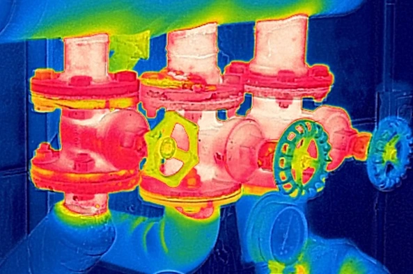
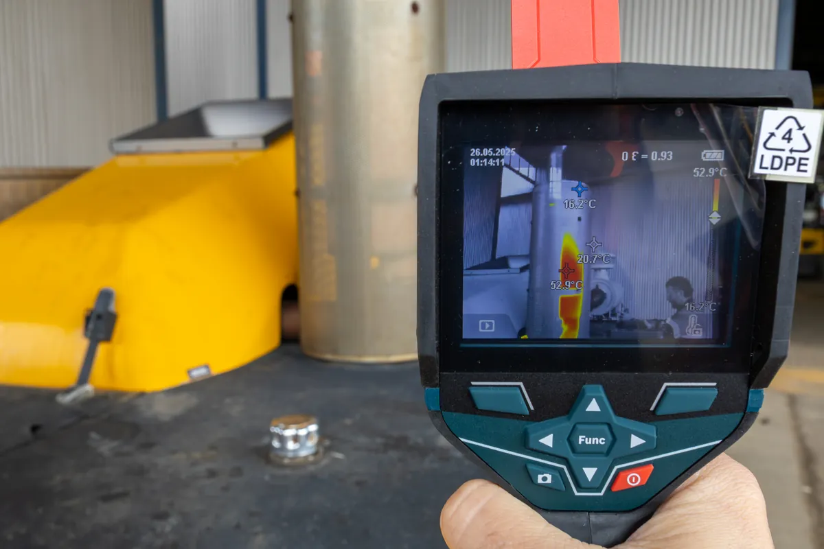
Dull, rough, oxidised and painted surfaces have high emissivity. They emit well, and the camera reads them reliably. Bare, polished or shiny metal has low emissivity. It emits poorly and reflects a lot of energy from its surroundings, so the camera largely sees reflections of other objects, including the person holding it.
That is why a polished stainless pipe, a bright aluminium cover or a freshly machined surface can read as far cooler than it really is, or can show a hot spot that is only a reflection of a light or a nearby hot pipe. The fault that matters can be hidden entirely.
Thermographers handle this in several ways: setting the correct emissivity in the camera for the surface being measured, measuring the reflected temperature and compensating for it, using reference spots of known high emissivity such as suitable tape or paint where access allows, and changing the viewing angle to avoid reflections. Surfaces that cannot be measured reliably are identified as such in the report.
Other Factors That Affect the Reading
Viewing angle. Emissivity falls at steep angles, so readings are most reliable when the camera faces the surface.
Distance and spot size. Every camera has a smallest area it can measure accurately at a given distance. A small component viewed from too far away is averaged with its surroundings and reads low.
Solar loading. Outdoor equipment in direct sun gains heat that has nothing to do with its condition. In a Hunter summer this can swamp the signal from a developing fault, so outdoor surveys are often timed for early morning, late afternoon or overcast days.
Wind. Wind cools surfaces and can hide a hot spot, particularly on small components.
Load. Heat from friction and resistance depends on load. Equipment should be surveyed at a representative operating load, and the load at the time should be recorded.
What is behind the surface. The camera reads surface temperature only. Insulation, cladding and refractory change what reaches the surface, which is why interpreting heat on insulated equipment needs care. Our article on thermography for condition monitoring of process plant covers this.
What a Reliable Thermography Report Contains
A report you can act on typically includes, for each finding: a thermal image and a matching visual image, the equipment identification and location, the temperatures measured and the reference used for comparison, the emissivity and reflected temperature settings, the operating load and environmental conditions, a severity ranking, and a recommended action. It should state the standards the survey followed, and list equipment that could not be surveyed and why.
Reports that follow the same format survey after survey are what make trending possible. For how this works on running plant, see our article on thermographic surveys of conveyors and rotating plant.
APEC Inspection is based in Newcastle and provides thermography services as part of a wider NDT offering that includes ultrasonic testing, visual inspection and coating inspection. We are accredited by NATA to ISO/IEC 17025:2017, and our non-destructive testing is carried out by technicians certified to ISO 9712 through AINDT. See our page on NDT across the Hunter Valley, or request a quote with the equipment you want surveyed and any standard your site requires.