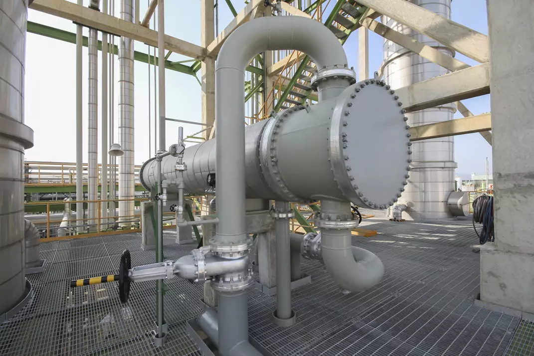
Testing Eddy Current for Heat Exchanger Tubes in Australia
Introduction: Why Eddy Current Testing Matters for Heat Exchangers
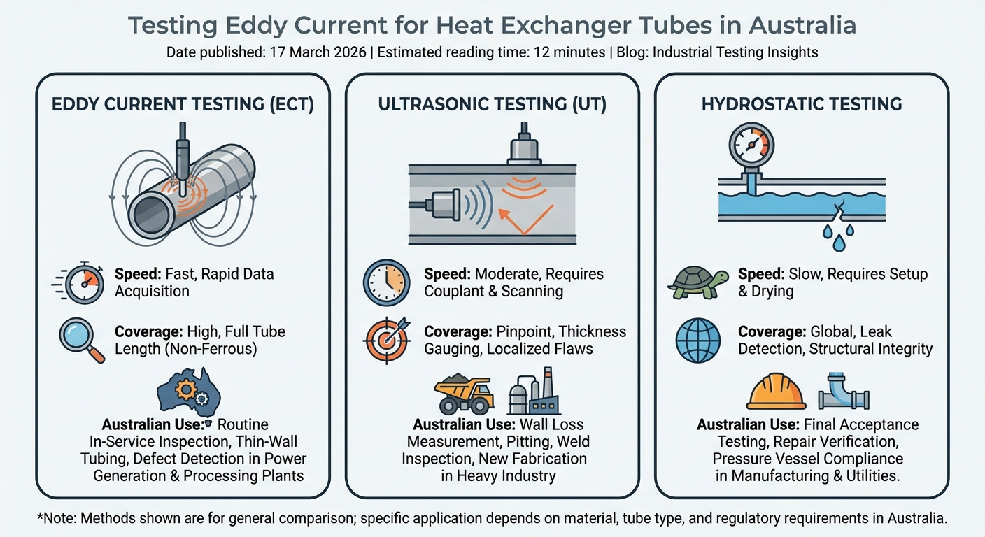
If you run heat exchangers, condensers or chillers, testing eddy current in your tubes is not optional. It is one of the fastest ways to understand tube health before leaks, trips and shutdowns hit your plant. However, some experts argue that calling eddy current testing “not optional” overstates the case. In practice, no Australian standard or regulation mandates eddy current as the only acceptable method for every heat exchanger, condenser or chiller. Techniques like ultrasonic testing (UT) and remote field testing (RFT) are also widely used, especially on ferromagnetic tubes where conventional eddy current is less effective. Under AS/NZS 3788, the choice of NDT method should come out of a risk assessment and take into account tube material, expected damage mechanisms and service conditions. In other words, while we strongly recommend eddy current as a fast, proven way to stay ahead of leaks and unplanned outages, it should sit within a broader toolbox of inspection options - not be treated as a one‑size‑fits‑all requirement.
In Australia, eddy current testing (ECT) sits at the heart of tube inspection programs in power, oil and gas, mining and heavy industry. The method is non‑destructive and relies on electromagnetic induction, so we can scan hundreds of tubes in a shift without cutting, drilling or pulling tubes out of the bundle, especially when it is integrated into broader non‑destructive testing services.
This guide walks through how ECT actually works inside a tube, the main techniques used on site, the types of defects we can (and cannot) pick up, and how ECT stacks up against ultrasonic and hydro tests. We also touch on realistic inspection intervals, cost drivers, and simple steps you can take to get better data out of every outage. The focus is squarely on real‑world Australian conditions and decision making, not textbook theory. For a broader overview of how specialist providers approach eddy current tubes inspection, these industry practices closely align with what is described here.
How Eddy Current Testing Works in Heat Exchanger Tubes
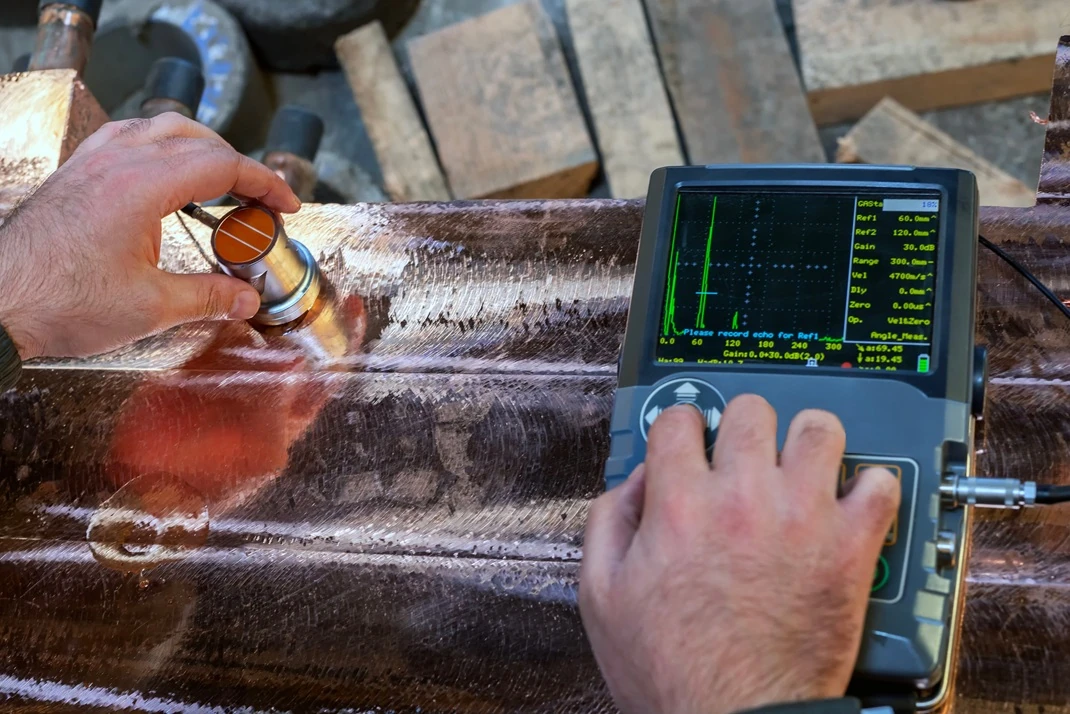
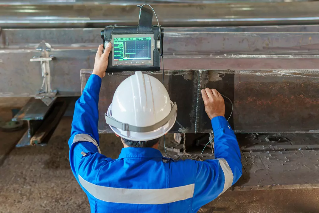
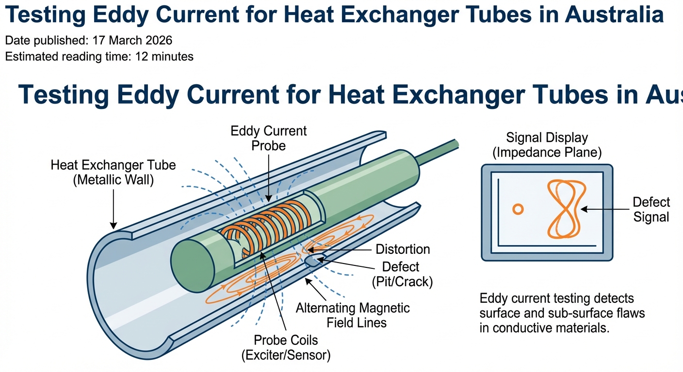
At its core, eddy current testing is about how a changing magnetic field interacts with a conductive tube wall. The probe we insert into each tube contains one or more coils. When we drive those coils with alternating current, they create an alternating magnetic field around the probe.
As the probe sits inside a copper, stainless or titanium tube, that changing magnetic field induces circulating electrical currents in the wall. These are the “eddy currents”. They flow in closed loops near the surface of the metal. Any change to the metal - a pit, a crack, wall thinning, even a dent - disturbs those currents, a principle reflected in detailed explanations from What is Eddy Current Testing?.
The instrument never “sees” the flaw directly. It measures the electrical impedance of the probe coil, a mix of resistance and inductive reactance. When eddy currents change, that impedance shifts. On the screen, those changes turn into loops or vectors whose amplitude and phase angle carry information about the defect type and depth.
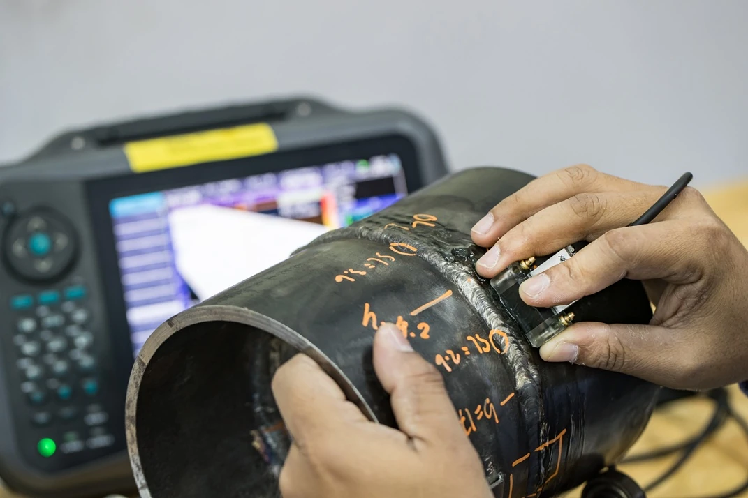
During a typical run, a bobbin probe is pulled through the tube at speeds on the order of 1 - 2 m/s using an automated push‑pull system, so a technician can realistically scan several hundred tubes per shift. We calibrate against a reference tube with known artificial defects before we start, so we can relate each signal pattern back to real wall‑loss percentages and depths. Without this calibration step, you are guessing at wall loss.
Skilled analysts then review the impedance plane data to separate support plate signals, deposits and real metal loss. By comparing phase, they can usually tell internal from external damage and distinguish a rounded pit from a tight crack, an approach consistent with specialist eddy current testing and inspection procedures. For organisations needing broader asset coverage, these tube inspections are often combined with aerial drone inspection services for hard‑to‑reach equipment and structures.
However, some experts argue that phase comparison alone is not always sufficient to categorically separate internal from external damage or to reliably distinguish all tight cracks from benign pits, especially in complex tube geometries or heavily scaled regions. In these more challenging scenarios, they recommend supplementing conventional eddy current analysis with additional techniques, tighter calibration standards or advanced signal modelling to reduce the risk of misinterpretation. In practice, this means working with experienced analysts, validating indications against historical data and, where necessary, confirming critical findings using complementary NDT methods to ensure asset integrity decisions are based on the most robust information available.
Key Eddy Current Techniques: Bobbin, RFT and Array
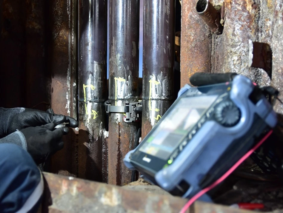
Eddy current testing for tubes is not one single technique. On site we normally choose between conventional bobbin ECT, remote field testing (RFT) and eddy current array (ECA) or near‑field array, depending on the tube material and damage mechanisms we expect, as outlined in many tube inspection eddy current applications.
For non‑ferromagnetic tubes - copper alloys, brass, cu‑ni, austenitic stainless and titanium - the workhorse is the bobbin probe. It has coils arranged symmetrically around the tube axis and is excellent for finding general corrosion, pitting and baffle plate wear. The big advantage is speed: we can scan hundreds to thousands of tubes in a single outage while still achieving good sensitivity to volumetric defects and moderate cracks.
When we move into carbon steel and other strongly ferromagnetic tubes, conventional ECT struggles because the magnetic permeability is high and the skin effect limits penetration. Here we switch to remote field testing. RFT uses a low frequency and a different coil spacing so the field travels through the wall and returns from the outside. The result is more uniform sensitivity through the full wall thickness and better performance on general wall thinning and through‑wall defects in steel.
Advanced array tools step in when you need more detail. Eddy current array and near‑field array probes carry multiple coils arranged around and along the tube, giving mapped C‑scan style images. They shine on axial cracks, complex wear at supports and fin‑fan tubes where conventional bobbin data becomes messy. In practice, a smart program often uses bobbin or RFT for fast screening, then brings in array probes on suspect tubes for higher resolution sizing and crack confirmation.
Choosing the right frequency is as important as picking the right probe. Higher frequencies are sensitive to small, near‑surface defects, while lower frequencies reach deeper and handle thicker walls better. On titanium, for example, we often work up in the megahertz range to strike the right balance between penetration and signal quality, a practice mirrored in eddy current testing of tubes across heavy industry. Providers that specialise in exchangers and pressure equipment often integrate these techniques with complementary services like storage tank inspection services and other in‑service equipment checks.
Defects, Detection Limits and When ECT Struggles
In non‑ferromagnetic heat exchanger tubes, eddy current testing is effective at picking up the problems that usually take you out of service. That includes internal and external pitting, general corrosion and erosion, fretting at support plates, axial stress corrosion cracks and broader wall thinning, which aligns with findings from The Eddy Current Testing of Heat Exchanger Tubes. Under good conditions, eddy current testing can reliably detect relatively small pits, but there is no universally accepted, standardized limit for minimum pit depth and diameter, so detection capability should be established and validated using job-specific calibration standards. Flat‑bottom style flaws can often be sized with good repeatability when the probe is well centred and the calibration tube closely matches the actual bundle material, although specific accuracy limits will depend on the procedure, equipment and site conditions. General wall loss shows up as smooth impedance loops whose shape and size track the amount of metal missing.
There are, however, hard limits. Very small volumetric pits, particularly those below about 10–20% wall loss, often approach the effective noise floor in real-world inspections, especially in noisy environments or in tubes with heavy deposits, which makes reliable detection and sizing much more difficult than in clean, laboratory conditions. Tight circumferential cracks are another challenge for simple bobbin probes because the coil geometry is not aligned to the crack. In those cases, array or rotating probes are more reliable for detection and sizing.
Deep damage also complicates life. Once you get beyond about 50% wall loss, ultrasonic signals can become noisy or complex and the precision of thickness sizing drops off, so measurements become less reliable. At that stage, the tube is normally a plugging candidate anyway, but it does affect remaining‑life calculations. Non‑conductive coatings, sludge, magnetite and scale can distort or mask indications if tubes are not cleaned properly before inspection.
Finally, classic ECT is designed for conductive materials. It brings little value on non‑conductive liners and performs poorly on high‑permeability ferromagnetic tubes unless you move to RFT or saturation techniques. For those tube bundles, forcing conventional ECT will only give you confusing data and false confidence. Where internal tube inspections are combined with surface condition checks, operators often supplement ECT with magnetic particle inspection on accessible ferromagnetic components.
Risk‑Based Inspection Frequency, Costs and Practical Tips
One of the questions I hear most is, “How often do we really need eddy current testing on these tubes?” There is no fixed calendar rule that suits every asset. Modern Australian practice follows risk‑based inspection rather than simple time‑based schedules.
Under AS 3788 for in‑service pressure equipment and aligned guidance like API 510, you consider both the likelihood and consequence of failure. Key inputs include tube material, cooling water chemistry, process fluid properties, temperatures, flow rates, operating hours, and actual corrosion rates from previous inspections. A condenser on an open seawater system with a history of pitting will land in a very different risk bucket to a clean, closed‑loop chiller.
As a rule of thumb, many Australian power stations schedule eddy current tube inspections on a risk-based 2–5 year cycle, typically aligned with major outages in line with AS/NZS 3788 requirements. Some high‑risk chillers and critical condensers are tested more often, even annually, if the consequence of a leak is high. Oil and gas plants often align tube inspections with 3 - 7 year shutdown cycles but tighten that window for exchangers in aggressive services.
Cost is another driver, but it has to be weighed against outage risk. Local providers report project ranges from around AUD $5,000 for small, simple jobs up to $50,000 or more for larger, more complex packages involving challenging access, travel and detailed data analysis. Pricing is usually per project, not per tube, because setup, mobilisation and reporting are a large part of the cost.
When you spread that cost over the number of tubes and compare it with the lost production from even a single forced outage, ECT almost always pays for itself. A sound approach is to do a baseline scan on new or refurbished exchangers, then use trend data and RBI to stretch or tighten intervals rather than locking into an arbitrary time frame, a strategy frequently applied to eddy current heat exchanger inspection programs. For plants across northern Australia, coordinating these RBI‑driven campaigns with local non‑destructive testing experts in Darwin and the Northern Territory can also help manage mobilisation and access costs.
Getting good eddy current data is not just about hiring a technician. Tube cleaning before the crew arrives matters: mechanical or chemical cleaning that removes scale, sludge and biofouling sharpens signal quality and improves sensitivity to small defects. Heavy deposits can hide pits and confuse support‑plate readings, so under‑cleaning is false economy.
Make sure the inspection plan matches your tubes. Confirm materials, wall thickness, diameter, and bundle layout from drawings and plant history so the NDT team can select suitable probes, choose the right frequencies, and prepare calibration tubes that replicate your equipment. When any of those inputs are wrong, sizing accuracy suffers.
Insist on clear, actionable reporting. A strong eddy current report should flag tubes for immediate plugging or removal, highlight patterns such as recurring wear at particular baffle plates, and recommend follow‑up such as IRIS checks on borderline indications. Digital tube‑sheet maps that you can compare from outage to outage turn one‑off inspections into a practical trend tool.
Treat each campaign as part of a long‑term trend, not a stand‑alone event. Store the raw data and summary tables in your asset management system. Over a few inspection cycles you will see which exchangers are stable and which are degrading fast, allowing you to time tube replacement, retubing or redesign before you hit an unplanned leak. For best results, coordinate tube inspections with your broader coating and inspection services so external corrosion protection and internal degradation are managed together, and draw on guidance from the phased array ultrasonic testing knowledge base when planning complementary UT coverage.
Conclusion and Next Steps
Eddy current testing gives Australian operators a fast, reliable way to see inside heat exchanger tubes without cutting them open or waiting for leaks. Used well, it lets you detect pitting, cracks and wall loss early, compare alternatives like IRIS and hydro tests sensibly, and build a risk‑based inspection plan that actually fits your plant.
The key is to match the technique to the tube material, clean properly, calibrate on realistic standards and track results over time. If you do that, ECT becomes a core tool for managing outage risk and extending asset life. When you plan your next shutdown, bring your inspection provider into the discussion early, share your tube history, and design an eddy current program that gives you hard data, not just pretty signals.
To learn more about the people and processes behind these inspections, you can read about NDT experts you can trust, explore the wider non‑destructive testing blog, or review how similar techniques are applied to pressure vessel integrity in complex plants.